Real -Time ECG Signal Acquisition and Processing Using LabVIEW
This is an Open Access article distributed under the terms of the Creative Commons Attribution Non-Commercial License(https://creativecommons.org/licenses/by-nc/3.0/) which permits unrestricted non-commercial use, distribution, and reproduction in any medium, provided the original work is properly cited.
Abstract
The incidences of cardiovascular diseases are rapidly increasing worldwide. The electrocardiogram (ECG) is a test to detect and monitor heart issues via electric signals in the heart. Presently, detecting heart disease in real time is not only possible but also easy using the myDAQ data acquisition device and LabVIEW. Hence, this paper proposes a system that can acquire ECG signals in real time, as well as detect heart abnormalities, and through light-emitting diodes (LEDs) it can simultaneously reveal whether a particular waveform is in range or otherwise. The main hardware components used in the system are the myDAQ device, Vernier adapter, and ECG sensor, which are connected to ECG monitoring electrodes for data acquisition from the human body, while further processing is accomplished using the LabVIEW software. In the Results section, the proposed system is compared with some other studies based on the features detected. This system is tested on 10 randomly selected people, and the results are presented in the Simulation Results section.
Keywords:
Electrocardiogram Signal Processing, NI myDAQ, NI LabVIEW Software, Data Acquisition, ECG Feature Extraction1. INTRODUCTION
Most people assume that wellness, which actually entails taking care of ourselves, indicates the absence of illness. In recent years, a drastic change has been experienced in the lifestyle of people worldwide in reference to the shift in their gastronomic patterns from consuming healthy to street foods and transitioning from fit to fat. This habit has increased the risk of many maladies, chief among which are cardiovascular diseases (CVDs).
With the loss of an estimated 17.9 million lives per year, CVDs are the primary cause of death globally. The menace of CVDs remains escalating, with more than 75% of these deaths occurring in developing countries [1]. CVD does not connote a single disease, but it is an illness that includes all the issues related to the heart and blood vessels of an individual. Some of the diseases under the umbrella of CVDs include arrhythmias and congestive heart failure. Although there are several approaches to detect these types of disease, the most commonly used method is the electrocardiogram (ECG) monitoring system [2].
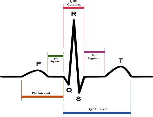
ECG refers to the recording of electric impulses of the heart muscles that are measured by small electrode patches that are attached to the human body, specifically on the skin of the arms, chest, and legs. ECG signal processing mainly includes three steps: 1- ECG data acquisition; 2- Signal preprocessing; and 3- Feature extraction. Cardiac cells are the muscle cells that form heart muscles [2]. These cells are electrically polarized in the normal state, and their insides are negatively charged. The fundamental electrical activity of the heart is depolarization, whereby cardiac cells lose their negativity. Depolarization occurs from cell to cell, building a wave of that can be transmitted across the whole heart. This depolarization wave builds an electric current flow, which is detectable through the use of electrodes. Upon the completion of depolarization, cardiac cells return to their normal polarity through a process called repolarization, which is also identifiable by the electrodes [3]. When acquiring ECG signals, some noise-like baseline wandering, powerline interference, and noise due to electrode movement also develop. Thus, we need to denoise (preprocess) the signal before using it for feature extractions, and the parameters responsible for this are the PR interval, PR segment, QRS interval, and ST segment [4], as shown in Fig. 1.
ECG results tell us about the heart rate and rhythm and inform us whether or not there is an enlargement of the heart due to high blood pressure (hypertension) or if there is any evidence of a previous heart attack (myocardial infarction) exists. ECG at rest is different from the ECG tested directly after exercising or if a person is in stress. In medical terms, the most efficient information about the heart rate can be obtained by a P wave, QRS complex, and T wave. A normal ECG signal is shown in Fig. 1.
In Fig. 1, five peaks and valleys are labeled as P, Q, R, S, and T. Proper ECG analysis depends on the accurate detection of these five waves only. To analyze an ECG signal, proper detection of the QRS complex is very important. Because using the QRS complex only, we can find the heart rate accurately, which is the most important parameter for heart issues [5]. The normal heart rate range lies between 60 and 100 beats per minute, and the formula for calculating the heart rate is shown as follows [5]:
| (1) |
ECG is a reliable process for diagnosing heart-related issues, saving the lives of many cardiac patients. However, in some emergency cases patients may die because of delays in diagnoses and the inability to obtain immediate medications and fast actions. Worldwide, studies are underway to develop some approaches and algorithms for the swift and optimized feature extractions that require minimum times for displaying results; however, until now, the optimum algorithm has not been achieved [6].
In the proposed system, a real-time ECG monitoring system is developed. Thus, the main objective of this research is to develop a system that can acquire ECG signals in real time and then extract features in no time. The method enables the recording and displaying of heart pulse rates and various ECG parameters, such as the P wave, PR interval, PR segment, QRS complex, and QT interval. The model helps to detect heart-related problems and displays it on the front panel of the Laboratory Virtual Instrument Engineering Workbench (LabVIEW) software.
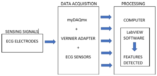
This paper also includes considerations regarding the notification of any arising heart-related problem, for example, a person would be aware of the affected part, i.e., the affected wave, segment, or interval with the help of rounded light-emitting diodes (LEDs) and displays. Through this system, one can know about the health of one’s heart, even before consulting the doctor. The system is divided into two parts: hardware and software. The block diagram of this system is shown in Fig. 2. The hardware component consists of the National Instruments (NI) myDAQ device, Vernier adapter, and ECG sensor, which are connected to ECG monitoring electrodes, for data acquisition from the human body. For the software part, NI LabVIEW is used. Notably, NI myDAQ is employed as a data acquisition device, whereas NI LabVIEW is adopted for display purposes, as well as to further process acquired data. In recent years, many researchers have worked on ECG classification using LabVIEW, and this section describes some of these efforts [7-11].
2. HARDWARE
The mainly used hardware components are ECG sensors, myDAQ device, and Vernier sensors.
2.1. Electrodes and ECG sensor BT36i
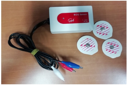
The electrical signals produced by the heart and measured on the skin are very weak [12]. Therefore, a good quality electrode, as well as proper and good contact between the skin and electrodes, is very important to obtain a good signal quality. Initially, ECG sensors determine the ECG signals from the body using electrodes patches pasted on some specific locations of the hands. The 3M monitoring electrode, 2223H, is used for sensing, and they are high quality patented solid gel conforms to the skin and the gel contains low chloride content that helps in less skin irritation and increases the comfort level of the patients. Then, the ECG BT36i sensor, with a memory chip with information about the sensor name, measured quality, unit, and calibration, comes into action, which measures the electrical potentials between 0–5 mV. These voltages are measured from the hands, specifically from the wrist and elbow where the 3M monitoring electrodes are pasted. This device has three wires to detect signals, and the colors of the connected clips are blue, red, and white. Hence, we need three electrodes to measure the signals, and two of them are pasted on both wrists, while the last one is placed on the elbow of the right hand. The electrodes used and ECG Sensor BT36i shown in Fig. 3. The blue clip is attached to the left-hand wrist electrode, while the red clip is placed on the right-hand wrist electrode, and the white clip on the right-hand elbow electrode.
2.2. NI myDAQ Device
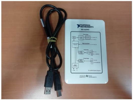
NI myDAQ is a low-cost data acquisition device, whereby one can acquire real-world signals. It features eight plug-and-play computer-based laboratory instruments when used with LabVIEW and includes digital multimeter and oscilloscopes. It is a compact device that provides analog (as well as digital) input/output, audio, and power supplies. The NI myDAQ device comes with a USB cable to connect it with the sensing device, audio and DMM cables, terminal connector, and a software CD. ECG sensor BT36i is connected to the myDAQ device using Vernier adapter to acquire real-world signals. The myDAQ device is shown in Fig. 4.
2.3. Vernier myDAQ Adapter
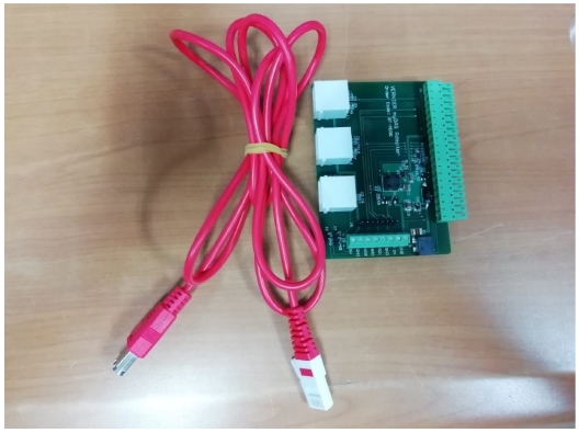
The Vernier Adapter (BT-MDAQ) allows us to connect the ECG sensor BT36i and NI myDAQ device. The adapter includes two connectors for analog sensors and one for digital sensors. A screw terminal and header pins provide access to myDAQ lines not used by the connector. Device sensors require a 5-V source, and the external power supply of 5 V is applied to the Vernier myDAQ device. Vernier myDAQ Adapter is shown in Fig. 5.
3. PROPOSED METHDOLOGY
LabVIEW was used for further processing, which was developed by National Instruments. It is a piece of graphical programming software that provides visualization of all the elements of an application, including hardware settings, measurement data, and debugging. LabVIEW is a software-based graphical programming language that consists of two panels: a front panel and a block diagram panel. Graphical programming is achieved at the block diagram panel. The front panel is an area where the user interface is created. In the front panel, all the outputs of the block diagram are shown. LabVIEW is also called virtual instruments (VI) because it is very much similar to the physical instruments used in the laboratories. One great advantage of VI is that we can make our desired system. Herein, LabVIEW was initially used to acquire ECG signals with the help of other hardware components, and then to extract the important ECG features with the help of “NI Biomedical Toolkit,” which allows for very efficient extraction of ECG features.
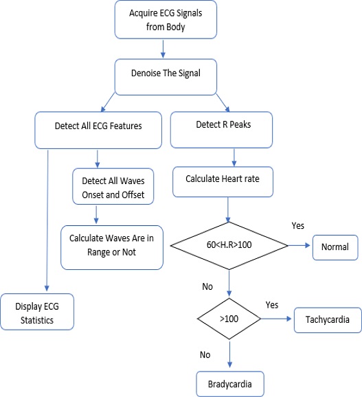
Next, the methodology used to design this system is explained. For good and accurate detection of ECG signal parameters, we need an algorithm that should be sufficiently efficient to properly acquire signals and perform the ECG signal feature extraction task correctly. Then, that algorithm should be applied in LabVIEW software to use it practically. The algorithm used herein is shown in Fig. 6 which contains the steps that are used in the algorithm as follows:
3.1. Acquire ECG Signals
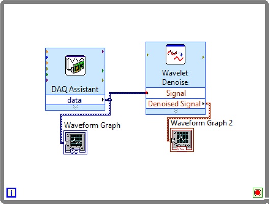
In the first step, ECG Signals are acquired from the individual’s body with the help of sensors and myDAQ device. The LabVIEW “DAQ Assistant” is used, and it is configured with the myDAQ hardware device to acquire ECG signals. At the time of measurement, the most important point is the sampling rate. The analog to digital and vice versa conversion depends on the determination of the scan rate in the myDAQ device. The fast sampling rate is better than the slow one because the representation of the raw signal is better in fast sampling. Slow sampling results in erroneously aliasing that outcome, which can lead to a mistake in reading the raw signals. So, to get rid of aliasing, the signal must be sampled at a rate greater than twice the frequency [13]. Herein, the frequency-rate is taken as 250 Hz, and there are 1000 samples to read. The maximum and minimum range of input signal is set to +5 V and -5 V, respectively. In the timing setting of the acquisition, the mode was opted as continuous samples. After selecting all these parameters in the DAQ assistant, the raw ECG signal acquisition from the body commences. The Block diagram to acquire raw ECG signals in LabVIEW is shown in Fig. 7, and the acquired raw ECG signals are shown in Fig. 10.
3.2. Denoising the ECG signal
Whenever we acquire signals from the real world, they carry some noise. This can be baseline wandering, channel noise, or motion artifacts, for example [14]. Baseline wander is a low-frequency noise that occurs due to body movement and respiration [15]. It creates problems in detecting peaks in the signal, especially R-peaks that are very important for the interpretation of the ECG signal. Herein, to remove these kinds of artifacts/noise “Wavelet Denoise” is used, and to remove the baseline wander, eliminating the trend of the ECG signal is necessary. For removing baseline wander and other noises from the raw ECG signal, the option for approximation is chosen as detrend, Thresholding rule is universal, soft thresholding is checked, wavelet is selected as db06, and transform type UWT (Undecimated Wavelet Transform) is chosen. The block diagram of the denoiser is shown in Fig. 7 and the denoise signal is shown in Fig. 11.
3.3. Detecting R-Peaks
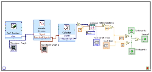
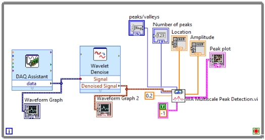
Herein, “Collector” and “WA Multi Peak Detection.vi” is used. The collector is used to display the heart rate and its status whether it is normal or suffering from tachycardia or bradycardia using some more VI’s and WA Multi Peak detection.vi is used to detect the R-peaks and display the same in the front panel.
R-peak detection is the most important part of ECG parameter research. Herein, the Teager energy method is used, which is based on squaring the signal amplitude. R-peaks have the highest amplitude, which is greater than 1 mV [5]. Thus, it can be detected efficiently with this method. After squaring “Bio-signal rate Extractor.vi” is used and the high and low threshold value is selected. A low threshold is selected as 2.5, and a high one as 3. In Peaks/Valley, peaks are selected as we need to find R-peaks. As output, it will show us the “number of cycles,” and we further apply Equation (1) to calculate the heartbeat rate:
After calculating the heartbeats, the system will indicate whether they are normal or affected with tachycardia or bradycardia. The block diagram of this part of the system is shown in Fig. 8.
WA Multiscale Peak Detection.vi is used to detect the R-Peaks, location and amplitude. Its block diagram is shown in Fig. 9, and the detected R-peaks shown in the front panel are presented in Fig. 10, 11, and 12.
In this step “3,” the most important parameter of ECG features, i.e., R-peaks, is detected, which can be used to find the correct heart rate and other important parameters. Since the R-peaks are detected, in further steps all other ECG features, such as the features related with P wave, PR interval, PR segment, QRS complex, ST segment, QT interval, T wave, Statistics, and whether or not the important waves are in range will be extracted using the NI Biomedical Toolkit.
3.4. Detecting All ECG Parameters
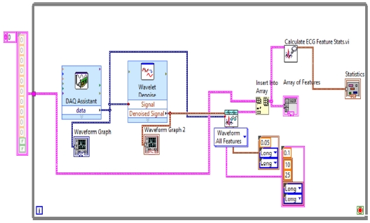
Here, in step “4,” all ECG parameters will be extracted using “ECG Feature Extaractor.vi,” where both the Raw ECG and denoised ECG are inserted. In the QRS detector parameters, the threshold factor is selected as 0.1, in frequency band low is 10 and high is opted as 25, QRS onset and offset are both set to long. In feature extractor parameters, isoelectric limit is 0.05, PR interval and QT interval are selected as long. In the selection type, “waveform all features” are selected. As the result or extracted features come into array format, the output of this is inserted into the “Insert into Array” and into the “Array of Features” for getting the features and also into the “Calculate ECG Feature Stats.vi” to obtain the statistics of the features because the dimensionality of the extracted features can be reduced by using statistics. The block diagram of the feature extractor is shown in Fig. 13.
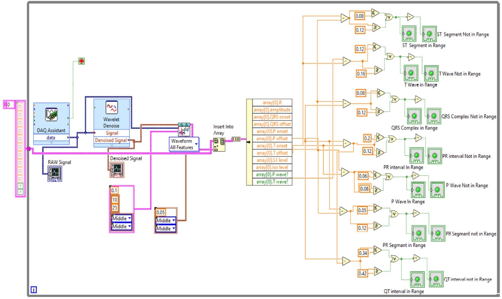
The extracted features are also inserted into an array to calculate whether the various intervals and segments are in range or not. The normal range of these segments and intervals is shown in Table 1.
With this normal range of ECG signals, we have calculated if the P wave, PR interval, PR segment, QRS complex, ST segment, QT interval, T wave are in range or not using Boolean and numeric expressions.
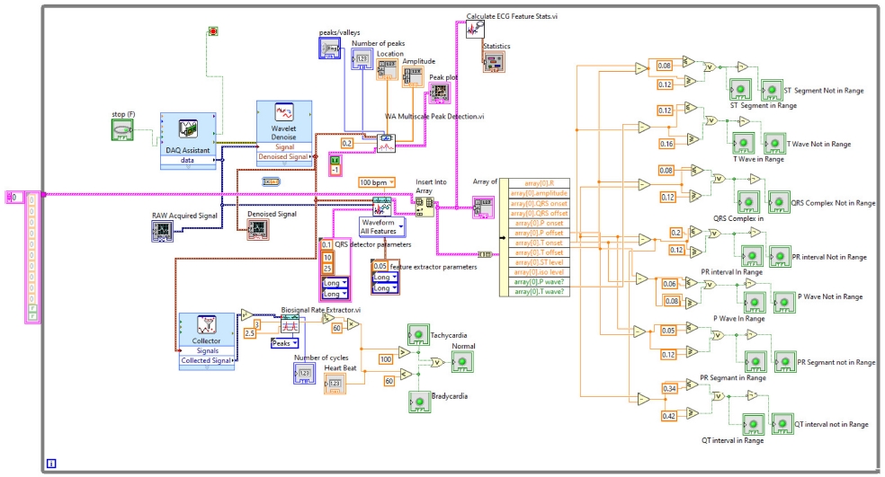
In the front panel, the results of these extracted features are shown with the help of the LED. The block diagram is shown in Fig. 14. All these above-mentioned steps were involved in the algorithm to detect the ECG features in real-time, and the full block diagram of this model is shown in Fig. 15. In the next section, the simulation results of the model are displayed.
4. SIMULATION RESULTS
The ECG signals are taken for 1 min from an individual’s body to evaluate the performance of the system, and it is tested on 10 randomly selected people. After 1 min, the values of the extracted ECG features are taken and displayed as a result.
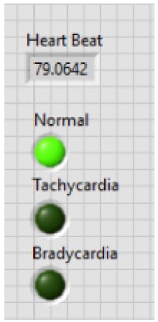
The first result is displayed after analyzing R-peaks and then automatically the LED light is blown and displays the heart condition, i.e., normal or suffering from tachycardia or bradycardia and calculates heart health based on some parameters depicted in Table 1. Based on Table 1, parameters heart rate of 10 people are taken and the result is shown in Table 2. In Fig. 16, the output of the heart rate detector is shown on the front panel of the modeled system. The heart rate detected to be 79 BPM; hence, the reason why the LED of the normal condition keeps blowing.
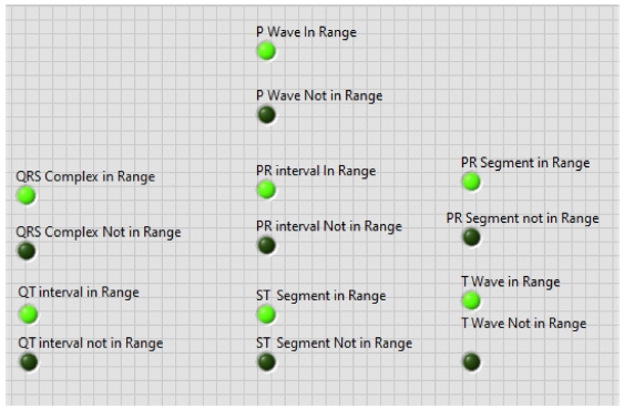
Second, the other ECG parameters, such as the P onset and P offset values of all the waves, are extracted. The sequential activation right and left atria are represented by a P wave. If P wave is absent in the signal and has a flat baseline, this indicates fine atrial fibrillation and sinoatrial arrest wave of atrial flutter. Detecting P wave is difficult because of its very low amplitude [16]. In QRS complex, if the duration is more than normal, it indicates hyperkalemia or bundle branch block. If the amplitude is increased more than normal, then it indicates cardiac hypertrophy. If the amplitude of Q wave is less than 1/3 of QRS or less than 1/4 of R wave, then it represents an abnormality in the presence of infraction. The T wave in ECG is for the representation of the repolarization of the ventricles. The normal range of all the waves of the ECG signal is shown in Table 3 [2,17]. By using the values from Table 3, all the waves are in their range or not are determined, and this is shown in the front panel of the system by using LED lights, as presented in Fig. 17.
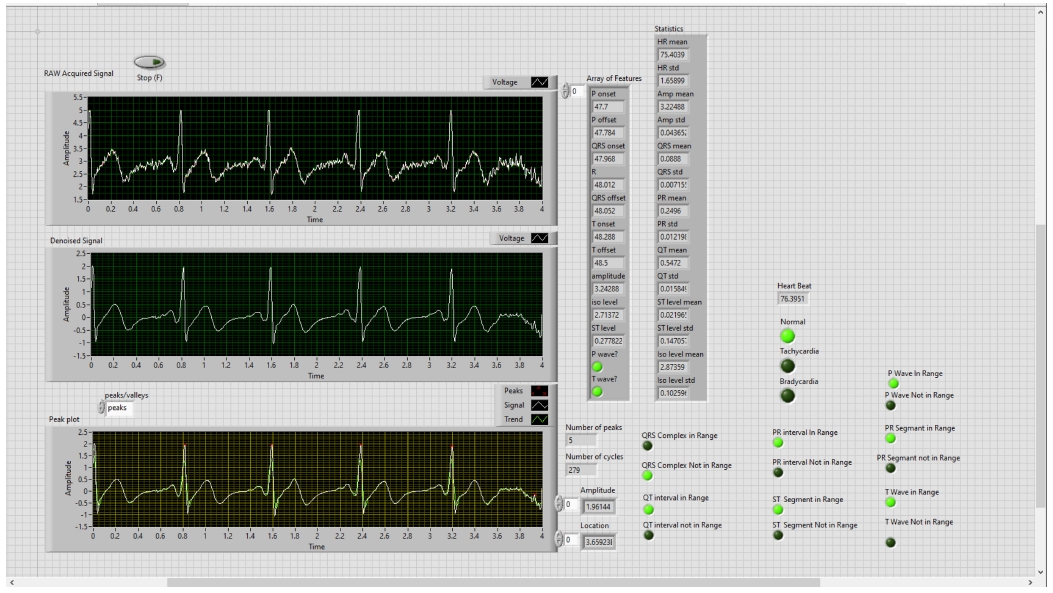
Adopting the system shown in Fig. 17, which gives output with LEDs, the patient can be aware of their heart condition, and in the case of any problem, he/she would be aware of the affected part of the heart, without the intervention of any doctor. The whole front panel output is shown in Fig. 18.
Tables 4 and 5 show the results of all extracted ECG parameters and statistics of 10 subjects. This system helps the patient to take cognizance of his/her heart problems, even before consulting the doctor, and this kind of system will help in many emergency cases also since the health of the heart can be known in no time, thereby representing a very convenient system for detecting ECG parameters. The proposed method is compared with some other previously developed methods, as shown in Table 6.
5. CONCLUSION
In the entire medical world, heart-related diseases are numerous, and the number of cardiac patients is also increasing on a daily basis. ECG is the most prominent approach for detecting diseases related to the heart. After analyzing the importance of ECG, the current scenario of the work herein is conducted.
In this paper, the ECG signals are acquired in real time from the real world using the myDAQ device and LabVIEW software. The system uses a 1-min ECG signal and denoises the signal using wavelet denoise simultaneously. After denoising, it extracts not only the heart rate but also other features of the ECG signal, such as R-peaks, P onset-offset, PR interval, PR segment, QRS complex, ST segment, QT interval, and T wave. Then, the system will also show the statistics of various parameters. Finally, employing the normal ECG parameter range system will indicate whether the various intervals, such as PR interval, and segments (including ST segment) are in the normal range.
The objective of acquiring ECG in real time to detect various ECG parameters and some diseases is successfully implemented by this paper, and this model was tested on 10 randomly selected subjects. The results and the comparisons with previously built methods are also shown in the Simulation Result section. The proposed system is user friendly, and anyone can use it to learn about their heart status, even before consulting a doctor. In the future, we can include more diseases related to the wave structure in the system. We can also use AI algorithms to make this system much better for further processing.
References
-
J. Huang, B. Chen, B. Yao, and W. He, "ECG Arrhythmia Classification Using STFT-Based Spectrogram and Convolutional Neural Network”, IEEE Access, Vol. 7, pp. 92871-92880, 2019.
[https://doi.org/10.1109/ACCESS.2019.2928017]

-
N. Keskes, S. F. Ghribi, R. Barioul, and N. Derbel, "Parameter Extraction of ECG Using Labview”, 15th Int. Multiconf. on Syst. Signals Dev., pp. 49-54, 2018.
[https://doi.org/10.1109/SSD.2018.8570391]

- C. Saritha, V. Sukanya, and Y. Narasimha Murthy, "ECG signal analysis using Wavelet Transforms”, Bul. J. Phys., Vol. 35, pp. 68-77, 2008.
- E. Haque and F. Ahmed, “ECG Signal Based Heart Disease Detection System for Telemedicine Application”, 1st Int. Conf. on Adv. Inf. Commun Technol, pp. 1-4, 2016
- A. N. Ay, M. Z. Yildiz, and B. Boru, “Real-time feature extraction of ECG signals using NI LabVIEW”, Sakaray Univ. J. Sci., pp. 576-583, 2017.
-
A. Sharma and H. P. Shukla, “Designing a simple toolbox for the early detection of arrhythmia, using advanced virtual instrumentation”, Biomed. Res., Vol. 30, No. 1, pp. 82-87. 2019.
[https://doi.org/10.35841/biomedicalresearch.30-18-1188]

-
D. Kaya, M. Türk, and T. Kaya, "Wavelet-based analysis method for heart rate detection of ECG signal using LabVIEW”, 40th Int. Conve. on Inf. Commun. Technol. Electron. Microelectron., pp. 314-317, 2017.
[https://doi.org/10.23919/MIPRO.2017.7973441]

-
S. Jain, P. Kumar, and M. M. Subashini, "LABVIEW based expert system for detection of heart abnormalities”, Int. Conf. on Adv. Electr. Eng., pp. 1-5, 2014.
[https://doi.org/10.1109/ICAEE.2014.6838451]

-
V. Nandagopal, V. Maheswari, and C. Kannan, “Newly Constructed Real Time ECG Monitoring System Using LabView”, Circuits Syst., Vol. 7. No. 13, pp. 4227-4235, 2016.
[https://doi.org/10.4236/cs.2016.713347]

- A. S. Vijoriya and R. Maheshwari, “ECG Signal Acquisition, Feature Extraction and HRV Analysis Using Biomedical Workbench”, Int. J. Adv. Res. Eng. Technol., Vol. 9, No. 3, pp. 84-90, 2018.
-
M. K. Islam, N. Haque, G. Tangim, T. Ahammad, and M. Khondokar, “Study and analysis of ECG signal using MATLAB & LABVIEW as effective tools”, Int. J. of Comput. Electr. Eng., Vol. 4, No. 3, pp. 404-408, 2012.
[https://doi.org/10.7763/IJCEE.2012.V4.522]

-
J. H. Lee and D. W. Seo, “Development of ECG Monitoring System and Implantable Device with Wireless Charging”, Micromachines, Vol. 10, No. 1, pp. 38(1)-38(15), 2019
[https://doi.org/10.3390/mi10010038]

- A. Kumar, L. Dewan, and M. Singh, “Real Time Monitoring System for ECG Signal Using Virtual Instrumentation”, WSEAS Trans. Biol. Biomed., Vol 3, No. 11, pp. 638-643, 2006.
- A. Velayudhan and S. Peter, “Noise Analysis and Different Denoising Techniques of ECG Signal - A Survey”, IOSR J. Electron. Commun. Eng., pp. 40-44, 2016.
-
Y. Luo, R. H. Hargraves, A. Belle, O. Bai, X. Qi, K. R. Ward, M. P. Pfaffenberger, and K. Najarian, “A Hierarchical Method for Removal of Baseline Drift from Biomedical Signals: Application in ECG Analysis”, Sci. World J., Vol. 2013, pp. 896056(1)-896056(10), 2013.
[https://doi.org/10.1155/2013/896056]

-
M. Rahimpour and B. M. Asl, “P wave detection in ECG signals using an extended Kalman filter: an evaluation in different arrhythmia contexts”, Physiol. Meas., Vol. 37, No. 7, pp. 1089–1104, 2016.
[https://doi.org/10.1088/0967-3334/37/7/1089]

-
R. Begum and R. Manza, “Detection of Cardiomyopathy using Support Vector Machine and Artificial Neural Network”, Int. J. Comput. Appl., Vol. 133, No. 14, pp. 29-34, 2016.
[https://doi.org/10.5120/ijca2016908178]

