동종 접합 InGaAs 수직형 Fin TFET의 온도 의존 DC 특성에 대한 연구
This is an Open Access article distributed under the terms of the Creative Commons Attribution Non-Commercial License(https://creativecommons.org/licenses/by-nc/3.0/) which permits unrestricted non-commercial use, distribution, and reproduction in any medium, provided the original work is properly cited.
Abstract
In this study, we evaluated the temperature-dependent characteristics of homojunction InGaAs vertical Fin-shaped Tunnel Field-Effect Transistors (Fin TFETs), which were fabricated using a novel nano-fin patterning technique in which the Au electroplating and the high-temperature InGaAs dry-etching processes were combined. The fabricated homojunction InGaAs vertical Fin TFETs, with a fin width and gate length of 60 nm and 100 nm, respectively, exhibited excellent device characteristics, such as a minimum subthreshold swing of 80 mV/decade for drain voltage (VDS) = 0.3 V at 300 K. We also analyzed the temperature-dependent characteristics of the fabricated TFETs and confirmed that the on-state characteristics were insensitive to temperature variations. From 77 K to 300 K, the subthreshold swing at gate voltage (VGS) = threshold voltage (VT), and it was constant at 115 mV/decade, thereby indicating that the conduction mechanism through band-to-band tunneling influenced the on-state characteristics of the devices.
Keywords:
tunneling, TFET, vertical, InGaAs, subthreshold swing, temperature-dependent1. 서 론
DNA, virus 등의 검사에 사용되는 실시간 검출 바이오 센서에는 민감도가 높은 트랜지스터가 사용된다. 수 십년 간, 금속 산화물 반도체 전계 효과 트랜지스터 (MOSFET) 소자는 집적도 향상 및 구조 혁신을 바탕으로 특성 개선을 실현시켰지만, Boltzmann 관계식의 제약을 받는 MOSFET 소자의 특성으로 인해, 공급 전압 (VDD)을 0.5 V 이하로 낮추는 것이 어렵다. 상온에서 60 mV/decade 이하의 문턱 전압 이하 스윙 (Subthreshold Swing, SS)의 특성을 가지는 터널 전계 효과 트랜지스터 (TFET)는 MOSFET을 대체 할 초저전력 소자 후보 중에 하나이며, 센서에 적용될 차세대 저전력 소자로써 TFET의 잠재력을 연구하고 있다[1,2]. 그러나 Si TFET의 두꺼운 터널링 장벽으로 인한 낮은 on current (ION)는 해결해야 할 병목 현상 중에 하나이다[3-5]. TFET의 ION을 개선하기 위해서 작은 유효 질량 (mn*) 과 밴드 갭 (Eg)을 가지는 물질을 활용하는 것이 필요하며, 결과적으로 InxGa1-xAs (x > 0.53) 및 AlSb/InSb와 같은 III-V 물질을 활용한 TFET이 해결책으로 주목을 받고 있다[6,7].
현재, 금속 유기 화학 기상 증착법 (MOCVD)을 이용한 상향식 공정은 III-V 기반 수직형 TFET 제작을 위한 주요 방식이다[8-12]. 상향식 공정 방식은 우수한 측벽을 형성할 수 있지만, MOCVD 기반 공정이 기존의 상보형 금속 산화물 반도체 (CMOS)공정과 호환되지 않고, 대량 제조에 적합하지 않다는 문제가 있다.
MIT 와 imec에서는 CMOS 공정과 호환이 가능한 하향식 공정방식을 활용하여 III-V 기반 수직형 나노선 TFET을 제작하고, 그 특성을 발표한 바가 있다[13,14]. 그런데, 수직형 나노선 형태의 소자의 경우, 전기적으로 분리된 소스, 드레인, 게이트 전극 형성을 위해 각 전극 사이에 절연막을 형성하는 것이 필수적인데, 이는 공정의 복잡도를 증가시키는 요인이다.
본 논문에서는 공정의 단순화를 위해 Fin 구조를 채택하였으며, 하향식 공정 방식으로 동종 접합 InGaAs 수직형 Fin TFET을 제작하였다. 전기 도금을 이용하여 나노핀 패턴을 형성하고, BCl3 기반 고온 ICP 공정을 통해 60 nm 폭을 가지는 InGaAs Fin을 형성하였다. 제조된 소자는 VDS = 0.3 V 에서 80 mV/decade의 SS 특성을 보여주었다.
TFET의 전류는 Shockley-Read-Hall (SRH) generationrecombination, Poole-Frenkel (PF), Band-to-Band Tunneling (BTBT)에 의해 결정되는데, 온도 의존 특성을 분석함으로써, 각성분의 영향을 분리 할 수 있다. 수평형 소자 및 수직형 나노선 소자에 대한 온도 의존 특성이 보고되었는데[15,16], 본 논문에서는 제작된 소자의 온도 의존 특성을 분석함으로써, 수직형 Fin TFET의 전류 구동 원리를 규명하였다.
2. 연구 방법
2.1 에피 구조 및 소자 공정
동종 접합 InGaAs 수직형 Fin-TFET 제작을 위한 에피층은 Semi-insulation InP 기판 상에 분자-빔-에피택시 (MBE) 방식으로 성장되었다. 에피층은 nm 두께 n+ In0.7Ga0.3As (Si 도핑, 5 × 1019 cm-3), 40 nm 두께 n+ In0.53Ga0.47As 드레인 영역(Si 도핑, 5 × 1019 cm-3), 100 nm 두께 진성 In0.53Ga0.47As 채널 영역, 300 nm 두께 p+ In0.53Ga0.47As 소스 영역(Carbon 도핑, 9 × 1019 cm-3) 및 300 nm 두께 진성 In0.53Ga0.48As 완충층으로 구성된다. 소자 제작은 본 연구실에서 기 발표한 논문과 동일한 방식으로 진행되었다[17].
2.2 동종 접합 InGaAs 수직형 Fin-TFET 특성
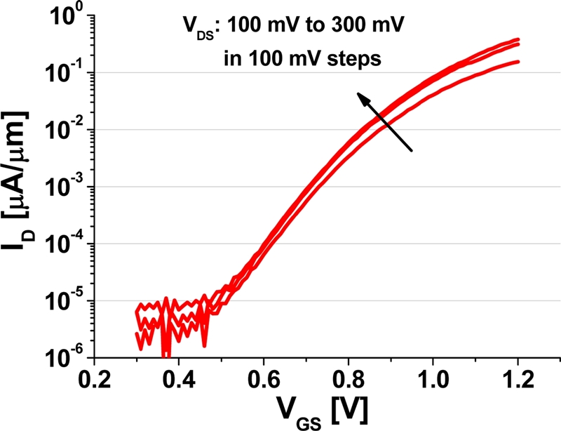
그림 1은 제조된 동종 접합 InGaAs 수직형 Fin-TFET 소자의 Subthreshold 특성을 보여준다. 제작된 소자는VDS = 0.3 V 일 때, 80 mV/decade의 SS 특성을 보여주었으며, 측정된 VGS 범위에서 IMAX/IMIN = 5.39 × 10⁴ 로, 우수한 On/OFF 특성을 보여주었다.
다음 장에서는 제작된 TFET 및 PIN diode의 온도 의존 특성 분석을 통해 전류 구동 원리를 규명하였다.
3. 결과 및 고찰
3.1 PIN diode의 온도 의존 특성
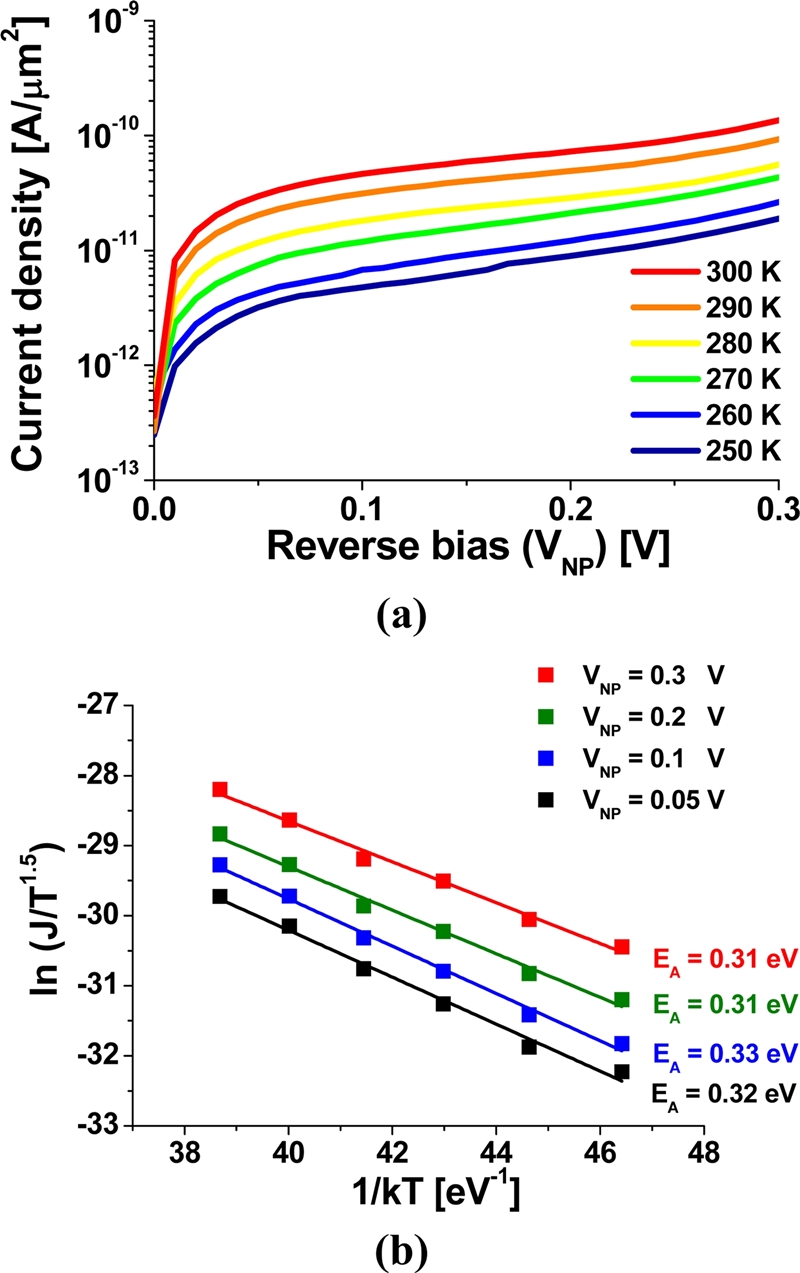
그림 2 (a)는 PIN diode의 역방향 바이어스 조건에서의 온도 의존 특성을 보여준다. 작은 역방향 바이어스에서는 SRH generationrecombination에 의해 PIN diode의 current가 결정된다. 이론적으로, SRH가 주요한 전류는 진성 반도체의 진성 캐리어 농도(ni)을 변수로 가지는 함수이다[18,19]. 진성 캐리어 농도는 Eg/2kT를 변수로 가지는 지수 함수로 표현 될 수 있다. 여기에서, Eg는 물질의 밴드 갭, k는 볼츠만 상수이며, T는 온도를 의미한다. 그림 2 (a)의 측정값을 활용하여 그림 2 (b)와 같이 Arrhenius plot을 그릴 수 있으며, 해당 그래프의 기울기를 구함으로써, 활성화 에너지 (EA)를 추출 할 수 있다. 측정을 통해 추출 된 EA는 VNP에 상관없이 0.32 eV이고, 이 값은 채널 물질인 In0.53Ga0.47As밴드 갭의 절반과 유사한 값을 가진다. 이는 에피 성장이 정상적으로 이루어 졌음을 의미하고, 이 결과를 TFET의 EA와 비교하여 분석하고자 한다.
3.2 InGaAs 수직형 Fin-TFET의 온도 의존 특성
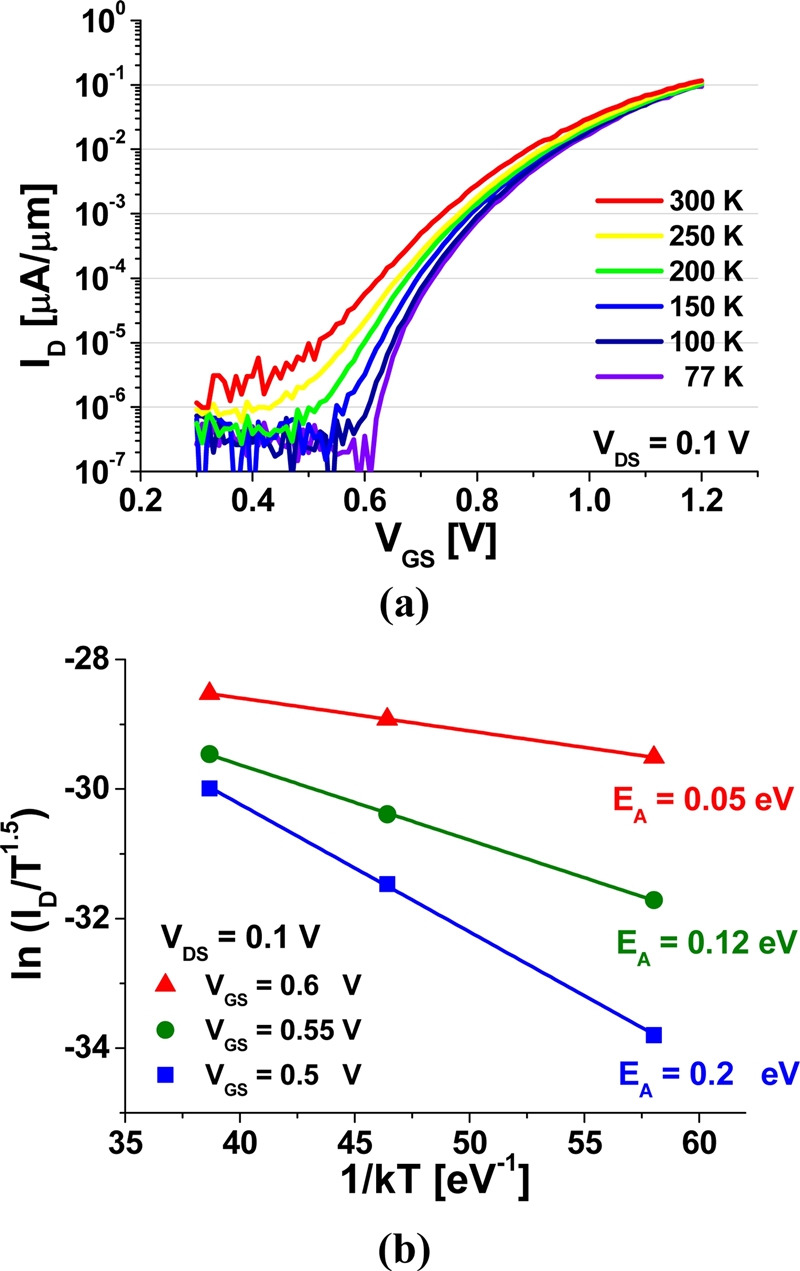
제조 된 동종 접합 InGaAs 수직형 Fin-TFET의 온도 의존 특성도 측정하였다. 그림 3 (a)는 VDS = 0.1 V일 때의 Subthreshold특성을 보여준다. 온도가 감소함에 따라 드레인 전류(ID)가 감소하는데, ID의 변화율은 작은 VGS에서 더 크다. 이는, VGS가 작을 경우 온도의 영향을 받는 SRH에 의한 전류가 주요하지만, 큰 VGS에서는 온도 의존성이 없는 BTBT에 의한 전류가 증가하기 때문이다. PIN diode와 마찬가지로, Arrhenius plot으로부터 EA를 추출 할 수 있으며, 그 결과를 그림 3 (b)에 나타내었다. VDS가 0.1 V로 일정 할 때, VGS = 0.5 V 에서 EA는 0.2 eV이며, VGS가 증가함에 따라 감소한다. 이는 VGS가 커질수록 BTBT에 의한 전류가 증가함을 의미한다. SRH 에 의한 전류가 주요한 영역 (VDS = 0.1 V, VGS = 0.5 V)에서 추출된 EA가 In0.53Ga0.47As 채널 밴드 갭의 절반과 일치할 것으로 예상하였지만, 그보다 작은 값이 추출되었다. 이는 구조적인 문제로 인해 드레인과 게이트 사이에서 발생한 누설 전류가 정확한 EA추출을 불가능하게 한것에 기인한다[20].

(a) Temperature-dependent subthreshold characteristics of the TFET and (b) extracted activation energy (EA).
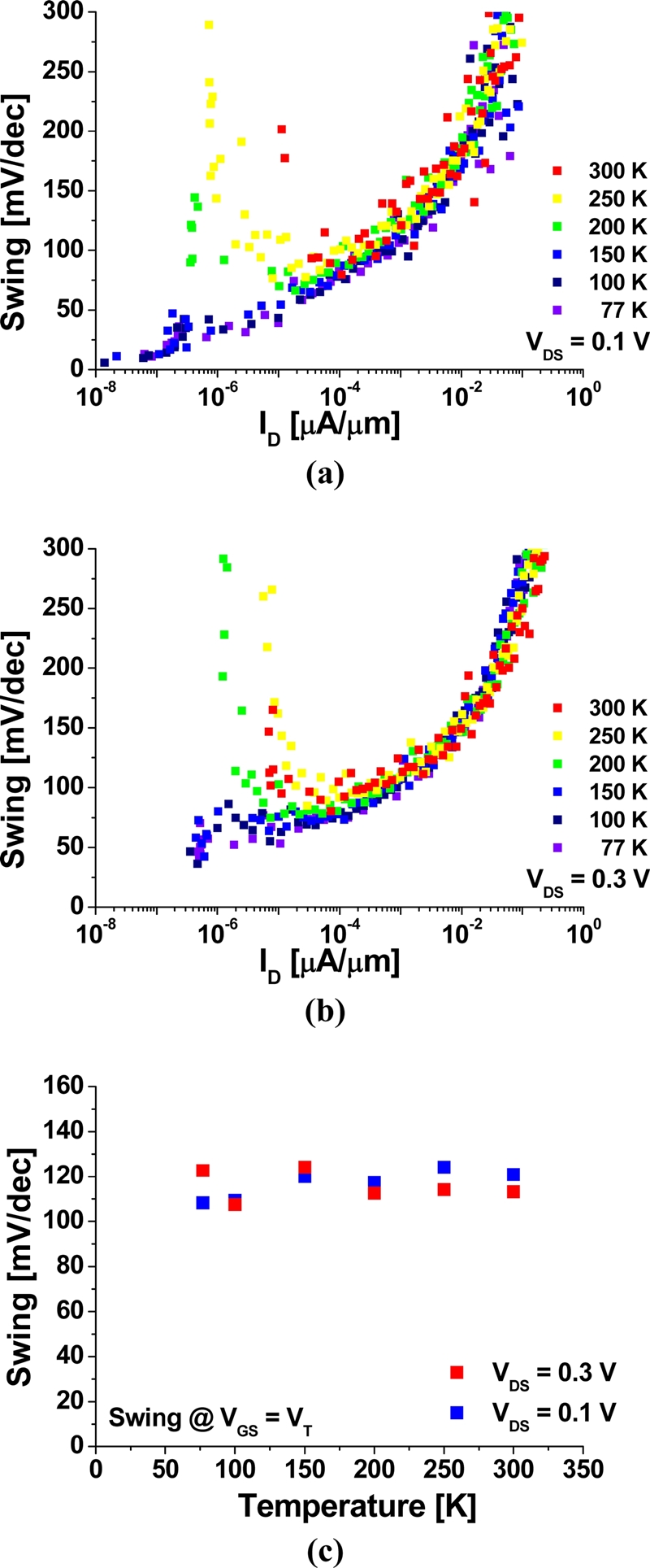
제작된 소자의 Subthreshold 특성을 자세히 분석하기 위해, 여러 온도 및 VDS에서의 SS값을 드레인 전류(ID) 에 대해 그린 결과를 그림 4 (a)와 (b)에 나타내었다. 온도가 감소함에 따라 드레인 전류의 최소값이 감소하기 때문에, 작은 ID영역에서 SS는 감소한다. 하지만, 드래인 전류가 1 nA/mm (VT는 ID가1 nA/mm일 때의 VGS) 이상일 때에는 SS가 온도에 상관없이 일정하다. 특히, VGS = VT 에서의 SS는 온도와 전압에 상관 없이 115 mV/decade로 일정한데 (그림 4 (c)), 이는 On 상태에서 전류가 온도 의존성이 없는 BTBT에 의해 발생됨을 의미한다.
4. 결 론
60 nm 폭을 가지는 동종 접합 InGaAs 수직형 Fin-TFET이 하향식 공정을 통해 제작되었다. 제작된 소자는 실온에서 80mV/decade 의 SS 및 우수한 On/Off 특성을 보여주었다. 제작된 TFET 소자 및 PIN diode의 온도 의존 특성을 분석함으로써, 전압에 따른 작동 원리를 명확하게 규명하였다.
Acknowledgments
이 논문은 2020 년도 정부 (과학기술정보통신부)의 재원으로 한국연구재단-나노·소재기술개발사업의 지원을 받아 수행된 연구임 (NRF-2017M3A7B4049517).
References
-
A. M. Ionescu and H. Riel, “Tunnel field-effect transistors as energy-efficient electronic switches”, Nature, Vol. 479, No. 7373, pp. 329-337, 2011.
[https://doi.org/10.1038/nature10679]

-
A. C. Seabaugh and Q. Zhang, “Low-voltage tunnel transistors for beyond CMOS logic”, Proc. IEEE, Vol. 98, No. 12, pp. 2095-2110, 2010.
[https://doi.org/10.1109/JPROC.2010.2070470]

-
F. Mayer, C. Royer, J. Damlencourt, K. Romanjek, F. Anderieu, C. Tabone, B. Previtali, and S. Deleonibus, “Impact of SOI, Si1-xGexOI and GeOI substrates on CMOS compatible tunnel FET performance”, in 2008 IEEE Int. Electron Devices Meet., pp. 1-5, San Francisco, USA, 2008.
[https://doi.org/10.1109/IEDM.2008.4796641]

-
A. Bowonder, P. Patel, K. Jeon, J. Oh, P. Majhi, H. Tseng, and C. Hu, “Low-voltage green transistor using ultra shallow junction and hetero-tunneling”, in Proc. IEEE Int. Workshop Junction Technol., pp. 93-96, Shanghai, China, 2008.
[https://doi.org/10.1109/SNW.2008.5418440]

-
K. Bhuwalka, S. Sedlmaier, A. Ludsteck, C. Tolksdorf, J. Schulze, and I. Eisele, “Vertical tunnel field-effect transistor”, IEEE Trans. Electron Devices, Vol. 51, No. 2, pp. 279-282, 2004.
[https://doi.org/10.1109/TED.2003.821575]

-
H. Lu and A. Seabaugh, “Tunnel field-effect transistors: State-of-the-art”, IEEE J. Electron Devices Soc., Vol. 2, No. 4, pp. 44-49, 2014.
[https://doi.org/10.1109/JEDS.2014.2326622]

-
M. A. Khayer and R. K. Lake, “Drive currents and leakage currents in InSb and InAs nanowire and carbon nanotube band-to-band tunneling FETs”, IEEE Electron Device. Lett., Vol. 30, No. 12, pp. 1257-1259, 2009.
[https://doi.org/10.1109/LED.2009.2034277]

-
H. Schmid, K. E. Moselund, M. T. Björk, M. Richter, H. Ghoneim, C. D. Bessire, and H. Riel, “Fabrication of Vertical InAs-Si Heterojunction Tunnel Field Effect Transistors”, in 69th Device Res. Conf., pp. 181-182, Santa Barbara, USA, 2011.
[https://doi.org/10.1109/DRC.2011.5994479]

-
H. Riel, K. E. Moselund, C. Bessire, M. T. Björk, A. Schenk, H. Ghoneim, H. Schmid, “InAs-Si Heterojunction Nanowire Tunnel Diodes and Tunnel FETs”, in 2012 IEEE Int. Electron Devices Meet., pp. 16.6.1-16.6.4, San Fransisco, USA, 2012.
[https://doi.org/10.1109/IEDM.2012.6479056]

-
K. Tomioka and T. Fukui, “Tunnel field-effect transistor using InAs nanowire/Si heterojunction”, Appl. Phys. Lett., Vol. 98, pp. 083114(1)-083114(3), 2011.
[https://doi.org/10.1063/1.3558729]

-
E. Memisevic, J. Svensson, E. Lind, and L.-E. Wernersson, “Vertical Nanowire TFETs with Channel Diameter Down to 10 nm and Point S MIN of 35 mV/Decade”, IEEE Electron Device. Lett., Vol. 39, No. 7, pp. 1089-1091, 2018.
[https://doi.org/10.1109/LED.2018.2836862]

-
E. Memisevic, M. Hellenbrand, E. Lind, A. R. Persson, S. Sant, A. Schenk, J. Svensson, R. Wallenberg, and L.-E. Wernersson, “Individual Defects in InAs/InGaAsSb/GaSb Nanowire Tunnel Field-Effect Transistors Operating below 60 mV/decade”, Nano Lett., Vol. 17, No. 7, pp. 4373-4380, 2017.
[https://doi.org/10.1021/acs.nanolett.7b01455]

-
X. Zhao, A. Vardi, and and J. A. Del Alamo, “Sub-Thermal Subthreshold Characteristics in Top-Down InGaAs/InAs Heterojunction Vertical Nanowire Tunnel FETs”, IEEE Electron Device. Lett., Vol. 38, No. 7, pp. 855-858, 2017.
[https://doi.org/10.1109/LED.2017.2702612]

-
A. Alian, S. E. Kazzi, A. Verhulst, A. Milenin, N. Pinna, T. Ivanov, D. Lin, D. Mocuta, and N. Collaert, “Record 47 mV/dec top-down vertical nanowire InGaAs/GaAsSb tunnel FETs”, in 2018 VLSI Symp. Tech. Dig., pp. 133-134, Honolulu, USA, 2018.
[https://doi.org/10.1109/VLSIT.2018.8510619]

-
M. Noguchi, S. H. Kim, M. Yokoyama, O. Ichikawa, T. Osada, M. Hata, M. Takenaka, and S. Takagi, “High Ion/Ioff and low subthreshold slope planar-type InGaAs tunnel field effect transistors with Zn-diffused source junctions”, J. Appl. Phys., Vol. 118, pp. 045712(1)-045712(15), 2015.
[https://doi.org/10.1063/1.4927265]

-
X. Zhao, A. Vardi, and J. A. Del Alamo, “InGaAs/InAs heterojunction vertical nanowire tunnel FETs fabricated by a top-down approach”, in 2014 IEEE Int. Electron Devices Meet., pp. 590-593, San Fransisco, USA, 2014.
[https://doi.org/10.1109/IEDM.2014.7047108]

-
J.-M. Baek, H.-B. Jo, D.-Y. Yun, I.-G. Lee, C.-S. Shin, H. Kim, D.-H. Ko, T.-W. Kim, and D.-H. Kim, “Vertical InGaAs tunnel-field-effect transistors by an electro-plating fin formation technique”, Solid-State Electron., Vol. 164, pp. 107681(1)-107681(5), 2020.
[https://doi.org/10.1016/j.sse.2019.107681]

-
Q. Smets, A. S. Verhulst, E. Simoen, D. Gundlach, C. Richter, N. Collaert, and M. M. Heyns, “Calibration of Bulk Trap-Assisted Tunneling and Schokely-Read-Hall Currents and Impact on InGaAs Tunnel-FETs”, IEEE Trans. Electron Devices, Vol. 64, No. 9, pp 3622-3626, 2017.
[https://doi.org/10.1109/TED.2017.2724144]

-
Y. Zhu, D. K. Mohata, S. Datta, and M. K. Hudait, “Reliability Studies on High-Temperature Operation of Mixed As/Sb Staggered Gap Tunnel FET Material and Devices”, IEEE Trans. Devices Mater. Reliab., Vol. 14, No. 1, pp 245-254, 2014.
[https://doi.org/10.1109/TDMR.2013.2255875]

-
H. Zhao, Y. Chen, Y. Wang, F. Zhou, and J. Lee, “InGaAs Tunneling Field-Effect-Transistors With Atomic-Layer-Deposited Gate Oxides”, IEEE Trans. Electron Devices, Vol. 58, No. 9, pp. 2990-2995, 2011.
[https://doi.org/10.1109/TED.2011.2159385]


