나노 입자 분리/분류를 위한 유전영동 칩 및 전극 패시베이션 기술 개발
This is an Open Access article distributed under the terms of the Creative Commons Attribution Non-Commercial License(https://creativecommons.org/licenses/by-nc/3.0/) which permits unrestricted non-commercial use, distribution, and reproduction in any medium, provided the original work is properly cited.
Abstract
Isolation and separation of biological nanoparticles, such as cells and extracellular vesicles, are important techniques for their characterization. Dielectrophoresis (DEP) based on microfluidic chips is an effective method to isolate and separate the nanoparticles. However, the electrodes of the DEP chips are electrolyzed by the electrical signals applied to the nanoparticles. Thus, the isolation/separation efficiency of the nanoparticles is reduced considerably. Through this study, we developed a microfluidic DEP chip for reliable isolation/ separation of nanoparticles and developed a passivation technique for the protection of the DEP chip electrodes. The electrode passivation process was designed using a hydrogel and the stability of the hydrogel passivation layer was verified. The fabricated DEP chip and the proposed passivation technique were used for the collection and dispersion of the fluorescent polystyrene nanoparticles. The proposed chip and the technique for isolation and separation of nanoparticles can be leveraged in various bioelectronic applications.
Keywords:
Dielectrophoresis chip, Electrode passivation, Nanoparticle, Isolation technique1. 서 론
생체 나노 입자는 약물 전달, 질병 진단 등과 같은 의료 분야 연구에 널리 활용되고 있고, 그 중에서도 엑소좀(exosome)과 같은 세포외 소포체 (EV)는 액상 생검법(liquid biopsy) 기반 암조기 진단을 위해 최근 많은 연구가 수행되고 있다 [1–2]. 이러한 생체 나노 입자의 다양한 특성을 분석하기 위해서는 체액 내에 포함된 생체 나노 입자를 고순도로 분리하고 이를 여러 기준에 따라 분류하는 기술이 필수적으로 요구된다.
시료로부터 원하는 나노 입자를 분리/분류하기 위한 대표적인 기존 기술로는 초원심분리(ultracentrifugation), 여과(filtering) 등이 있다. 초원심분리는 높은 분리 효율과 재현성을 가지지만, 다량의 시료를 필요로 하고 분리 시간이 오래 걸리며 여러 종류의 나노 입자가 혼합되어 있을 때 각각을 개별적으로 분리하는 것이 어렵다 [3-5]. 여과 방법은 나노 입자의 분리 속도가 빠르지만 시료의 손실이 많다는 한계가 있다.
최근에는 microfluidic chip에서 나노 입자를 분리하는 연구가 많이 진행되고 있다. 대표적으로 연구되는 나노 입자 분리/분류방법으로는 자기영동(magnetophoresis), 전기 영동(electrophoresis), 및 유전영동 (dielectrophoresis, DEP) 등이 있다 [6-10]. 자기영동은 외부 자기장을 이용한 자성 입자 제어 기술을 의미하며 비접촉식으로 나노 입자를 제어할 수 있다는 특징이 있다. 이 기술은 소자 설계가 간단하다는 장점이 있으나 세포와 같은 생체입자의 경우 자성이 약해 자기력을 유도하기 힘들다고 알려져있다. 전기영동은 자기영동과 유사하게 외부 전기장을 이용한 대전 입자 제어 기술인데, 인가되는 신호에 의해 생체 입자가 손상될 수 있으며 전극이 전기 분해되면서 손상되어 분리 효율이 낮아질 수 있다.
유전영동은 극성이 없는 입자가 불균일한 전기장 내에서 극성이 유도되어 전기장 변화율에 따라 특정 방향으로 힘을 받는 현상이다 [11]. 이 때 입자에 작용하는 힘을 유전영동력(DEP force)이라 부르며 이 힘은 입자의 크기, 입자 주변 매개의 전기 전도도 (electrical conductivity) 및 유전율(dielectric constant), 전기장 변화율 및 주파수에 따라 다르게 작용한다. 유전영동력은 수식 (1)과 같이 표현된다 [12].
| (1) |
R과 εm은 각각 입자의 반지름 및 매개의 유전율을 나타낸다. fCM은 Clausius-Mossotti(CM) factor로 불리며, 수식 (2) 와 같이 정의될 수 있다.
| (2) |
수식 (2)에서 εp* 및 εm*는 각각 입자 및 매개의 복소 유전율을 나타낸다. 각각의 복소 유전율 식은 수식 (3)과 같이 표현될 수 있다.
| (3) |
여기서 σ는 전기 전도도, ω는 인가 신호의 각주파수이다. CM factor의 실수부를Re(fCM)으로 표현할 수 있고, 이 값의 부호에 따라 입자가 받는 힘의 방향이 결정된다. 예를 들어 Re(fCM) > 0일 경우, 입자가 받는 힘은 positive-DEP(pDEP) 가 되어 전기장의 변화율이 큰 쪽으로 움직이게 되고, Re(fCM) < 0인 negative-DEP(nDEP)의 경우에는 전기장의 변화율이 작은 쪽으로 힘을 받아 움직이게 된다. 특정 입자가 특정 매개에 현탁되어 특정 소자에 주입된 경우 수식 (1)에서 Re(fCM) 외의 나머지 값들은 상수가 되기 때문에 주파수를 조절하여 입자의 움직임을 제어할 수 있게 된다. 이러한 유전영동 기술은 극성 유도가 가능한입자에 모두 적용 가능하여 세포 및 다양한 생체 나노 입자의분리/분류 등에 활용될 수 있다는 장점이 있다. 그러나 유전영동 기반 나노 입자 분리 역시 전기영동 기술과 유사하게 전극이 전기 분해로 인해 손상될 수 있어 시간에 따라 나노 입자 분리 효율이 감소하게 된다. 하지만 유전영동은 전기영동과 달리 교류 신호를 이용하기 때문에 전기 분해에 의한 전극 손상 정도가 더 작다. 따라서 전극의 손상을 줄일 수 있는 passivation layer를 전기영동 chip보다 유전영동 chip에 적용하는 것이 더 효율적이고, 안정적인 나노 입자 분리를 반영구적으로 수행할 수 있다. 전극 passivation에 활용될 수 있는 물질들 중 hydrogel은 폴리머 고분자 사슬로 이루어진 물질로 수용액에 용해되지 않으며 화학적으로 안정하다. 대부분의 생체 나노 입자는 물 기반 용액에 포함되어 있기 때문에, hydrogel은 생체 나노 입자의 안정적인 분리/분류를 위한 전극 passivation에 매우 적합한 물질이다.
본 연구에서는 나노 입자를 정확하면서도 안정적으로 분리/분류할 수 있는 유전영동 기반 microfluidic chip (DEP chip)을 설계하고, DEP chip의 전극 손상을 최소화할 수 있는 hydrogel 기반 전극 passivation 기술을 개발하였다. 반도체 공정을 이용하여 DEP chip의 전극 및 채널을 제작하고, 전극 passivation 효율이 가장 높은 hydrogel 농도 조건 및 코팅 조건을 결정하였다. 그 후 생체 물질의 용매로 가장 많이 사용되는 액체 중 하나인 phosphate-buffered saline (PBS)에 형광 polystyrene(PS) bead를 희석시킨 용액을 hydrogel이 코팅된 DEP chip 내에 주입하고, DEP chip에 특정 주파수의 교류 신호를 인가하여 bead에 유전 영동력을 인가하는 실험을 진행하였다. 그 결과 PS bead가 전극 근처로 모이거나(capture), 전극에서 멀어지는(release) 현상을 확인하였다. 개발된 DEP chip 및 전극 passivation 기술은 세포 및 EV와 같은 다양한 생체 입자들의 분리/분류에 적용될 수 있어 추후 암 치료 및 진단을 위한 연구 분야에 널리 활용될 수 있을 것으로 기대된다.
2. 연구 방법
2.1 Microfluidic DEP chip 제작
DEP chip을 제작하기 위해 먼저 e-beam evaporation 공정을 통해 Ti(10 nm) 및Au(50 nm)를 증착하였다. 그 후photolithography 공정 및 standard gold etchant (Sigma-Aldrich)와 SC-2 용액을 이용한 Au 및 Ti wet etching공정을 통해 slide glass 위에 폭이100 μm, 간격이 200 μm 인 comb 형태의 전극을 patterning하였다.
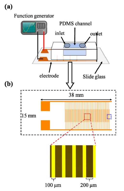
4-inch wafer에 photolithography 공정과 BOE 및 TMAH 용액을 이용한 SiO2 및 Si wet etching공정을 진행하여 두께가 34 μm인 PDMS 채널 제작을 위한 mold를 제작하였다. PDMS monomer와 경화제를 10:1 w/w 비율로 혼합하고 이를 mold에 부어 80 oC에서60분 동안 경화시킨 후 cutting 및 inlet/outlet punching과정을 진행하여 PDMS 채널을 제작하였다. 전극이 patterning 된slide glass와 제작된 PDMS 채널을 O2 plasma 처리를 통해 bonding하여 microfluidic DEP chip을 제작하였다(Fig. 1).

(a) Schematic of a microfluidic dielectrophoresis (DEP) chip. The PDMS channel was bonded with a glass substrate that comb-structured two electrodes are patterned. To apply the DEP force to nanoparticles, a function generator was connected with two metal pads and an AC voltage was applied to the electrode. (b) Schematic and optical image of electrodes. In an electrode-overlapped region (red rectangular), the width of electrode is 100 μm and the interval between two electrodes is 200 μm. Blue rectangular indicates a region in which an electric-field gradient was simulated (detailed in Fig. 2)
2.2 DEP chip을 이용한 나노 입자 capture/release 방법
Fig. 1과 같이 comb 구조의 전극이 patterning된 DEP chip에 500 nm 크기의 PS bead(FCDG005, Bangs Laboratories, Inc.)가 현탁된 PBS 0.1X 용액 4 μL를 주입하고 함수 발생기(AFG-2105, GW Instek)를 금속 패드 영역에 연결하였다. DEP chip에 5 Vpp, 1 kHz의 교류 전압을 인가하고 공초점 현미경 (LSM 800, Carl Zeiss)을 이용하여 PS bead의 capture 현상을 관찰하였다. 그후 DEP chip에 5 Vpp, 1 MHz의 교류 전압을 인가하고 공초점 현미경을 통해 PS bead의 release 현상을 관찰하였다.
2.3 시뮬레이션(COMSOL, MATLAB)
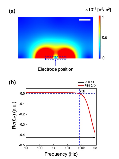
COMSOL 시뮬레이션 tool을 이용하여 microfluidic DEP chip의 전극과 동일한 dimension을 구현하고 전극 주변 영역에서의 전기장 변화율의 분포를 확인하였다 (Fig. 2(a)). 전극의 가장자리 주변 영역이 다른 영역에 비해 상대적으로 전기장 변화율이 큰 것을 확인할 수 있다. 나노 입자에 인가되는 pDEP 힘은 전기장 변화율이 큰 쪽으로 나노 입자를 당기기 때문에, 전극의 가장자리 쪽에 나노 입자가 capture될 것으로 예상할 수 있다.

(a) The COMSOL simulation result of electric-field gradient around the electrode of the DEP chip. The electric-field gradient is relatively large at the edge of electrode (scale bar: 50 μm). (b) The MATLAB simulation results of the Clausius-Mossotti(CM) factor for polystyrene(PS) bead in phosphatebuffered saline (PBS) 1x solution (black line) and 0.1x solution (red line).
Fig. 2(b)는 500 nm크기의 PS bead가 PBS 1X 및 0.1X 용액에 현탁되어 있을 때 주파수에 따른 Re(fCM) 값을 MATLAB으로 시뮬레이션한 결과이다. PS bead의 알려진 유전율(~ 2.6) 및 전기 전도도(~ 1.6 mS/cm)와 PBS 용액의 알려진 유전율(1X, 0.1X: ~ 80) 및 전기 전도도(1X: ~ 15.2 mS/cm, 0.1X: 1.52 mS/cm)를 이용하여 10 Hz에서 1 MHz 사이의 주파수 범위에서 Re(fCM) 값의 경향을 확인했다. PS bead가 PBS 1X 용액에 현탁된 경우 Re(fCM) 값은 항상 음수인데, 이는 시뮬레이션된 주파수 범위에서는 PS bead에 항상 nDEP 힘만이 작용한다는 것을 의미한다. 그러나, PS bead가 PBS 0.1X 용액에 현탁된 경우에는 73 kHz 이하의 주파수에서 Re(fCM) 값이 양수임을 확인할 수 있다. 이는 PBS 0.1X 용액 내의 PS bead에 73 kHz 이하의 교류 신호가 인가되면 PS bead에 pDEP 힘이 작용하여 PS bead가 전극 근처로 capture될 수 있음을 의미한다.
2.4 Hydrogel 코팅
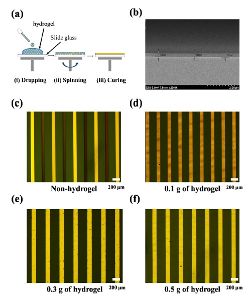
Fig. 3(a)는 hydrogel passivation layer 코팅 과정을 개략적으로 보여준다. Hydrogel powder (0.1 g, 0.3 g, 0.5 g)와 에탄올 5mL를 혼합하고 60 oC에서 300 rpm의 속도로 1시간 동안 stirring하여 hydrogel powder를 에탄올에 완전히 용해시킨다. 전극이 patterning된 slide glass 위에 hydrogel이 용해된 에탄올을 dropping하고 5,000 rpm의 속도로 2분 간 spin 코팅하여 hydrogel layer를 전극 위에 균일하게 올려준다. 그 후 hydrogel layer와 전극 표면의 접착력(adhesion)을 높이기 위해 80 oC에서 10분 간 hydrogel layer를 경화시킨다.

(a) Procedures for hydrogel coating on the electrode of the DEP chip. (i) The hydrogel suspended in ethanol was dropped on the glass substrate and (ii) spin-coated with 5,000 rpm for 2 min and (iii) dried at 60 oC for 10 min. (b) SEM image of the glass substrate coated with hydrogel. The thickness of hydrogel was uniformed (average thickness: ~ 268 nm). (c) – (f) Optical images of the electrodes (c) hydrogel was not coated, (d) 0.1 g of hydrogel was coated, (e) 0.3 g of hydrogel was coated, and (f) 0.5 g of hydrogel was coated. The DEP chip was filled with PBS 0.1X solution and an AC signal (5 Vpp, 1 kHz) was applied for 4 min.
Fig. 3(b)는 전극 위에 코팅된 hydrogel layer를 확인한 SEM 이미지이다. Hydrogel layer의 평균 두께는 약 268 nm이고 slide glass 전반에 걸쳐 두께 편차가 크지 않음을 확인되었다.
3. 결과 및 고찰
3.1 Hydrogel을 이용한 microfluidic DEP chip의 전극 passivation
DEP chip을 이용하여 나노 입자를 정확하면서도 안정적으로 분리/분류하기 위해서는 전극이 전해 용액과 직접 접촉하는 것을 방지하면서도 전기 신호가 손실 없이 나노 입자에 인가될 수 있어야 하고, 이를 위해 전극 위에 passivation layer를 올리는 과정이 요구된다. Fig. 3(c)는 전극 위에 hydrogel layer를 코팅하지 않은 DEP chip에 PBS 0.1X 용액을 주입하고 5 Vpp, 1 kHz의 교류 전압을 4분 간 인가했을 때의 광학 현미경 이미지로, 전극 손상을 직관적으로 확인할 수 있다. 전기 분해로 인한 전극의 손상은 곧 나노 입자의 분리/분류를 위한 DEP chip의 기능 상실을 의미하기에, 전극 passivation layer의 코팅이 반드시 필요하다는 것을 Fig. 3(c)를 통해 판단할 수 있다.
Fig. 3(d) – 3(f)는 hydrogel의 농도에 따른 hydrogel layer의 전극 passivation 효율을 보여준다. 에탄올 5 mL에 hydrogel powder를 0.1 g, 0.3 g, 0.5 g의 3가지 조건으로 나누어 용해시키고 전극이 patterning된 slide glass에 이를 코팅한 후 5 Vpp, 1 kHz의 교류 전압을 4분 간 인가하였다. 여기서 4분은 공초점 현미경의 촬영 영역 내의 PS bead중 90% 이상이 전극으로 capture되는 적정 시간으로(Fig. 4 참고), 교류 신호를 이보다 긴 시간동안 인가할 경우 hydrogel이 떨어져 나가거나 전극이 손상되어 나노 입자의 분리/분류 효율을 감소시킬 수 있다. Fig. 3(d)에서 확인할 수 있듯, hydrogel 0.1 g 조건에서 DEP chip의 전극은 Fig. 3(c)에서의 전극보다는 그 정도가 약하지만 전반적으로 손상된 것을 확인할 수 있다. Fig. 3(e)는 hydrogel 0.3 g 조건에서의 전극 손상 정도를 보여주는데, 전극의 극히 일부 영역에서 움푹 패인 것으로 확인되는 형상이 관측되었다. 그러나 Fig. 3(d)의 전극과 달리 이 영역에서 Au의 고유 색이 유지되는 것으로 보아, 전극이 손상된 것이 아니라 hydrogel layer의 일부가 손상된 것으로 추정된다. 손상된 hydrogel은 나노 입자를 포함하는 용액에 섞일 수 있으나 이는 용액의 부피에 비해 무시될 수 있을 정도로 작은 양이고, 대부분의 경우 hydrogel과 나노 입자의 유전율 및 전기 전도도가 큰 차이를 보이기 때문에 나노 입자의 분리/분류 효율에 미치는 영향은 미비할 것으로 예상할 수 있다. 이로 보아 hydrogel 0.3 g 조건은 DEP chip의 전극 passivation에 비교적 적합한 조건임을 유추할 수 있다. Fig. 3(f)는 hydrogel 0.5 g 조건에서의 전극 손상 정도를 보여주는데, Fig. 3(e)의 전극과 달리 움푹 패인 영역도 확인되지 않는 것을 알 수 있다. 또한 본 연구팀은 hydrogel 1.0 g 조건에서도 위와 동일한 실험을 수행하였는데, hydrogel이 용해된 에탄올의 점성이 너무 높아 전극 위에 균일하게 코팅되지 않는 것을 확인하였다. 위의 결과들을 종합하였을 때, DEP chip의 전극 passivation에 가장 적합한 hydrogel 농도 조건은 0.5 g임을 판단할 수 있다.
3.2 Microfluidic DEP chip 및 전극 passivation 기술을 이용한 PS bead capture/release
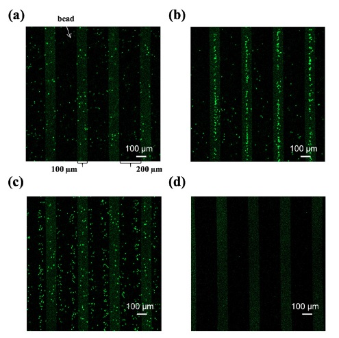
전극 passivation을 위한 hydrogel 코팅 조건을 DEP chip에 적용하고, 이 chip을 나노 입자의 capture/release에 활용해 보았다. Fig. 4(a)는 PBS 0.1X 용액에 현탁된 500 nm 크기의 형광 PS bead 시료를 microfluidic DEP chip에 주입하고 공초점 현미경을 이용하여 chip 내 bead를 관찰한 이미지이다. 본 실험에서 사용한 PS bead는 480 nm 파장의 빛에 의해 여기(excitation)되어 520 nm 파장의 빛을 방출하기 때문에, Fig. 4(a)에서 확인할 수 있듯이 초록색의 작은 점으로 관찰된다. 이미지에서 직사각형 형태로 반복되어 관찰되는 옅은 초록색의 패턴은 DEP chip의 전극으로, 100 μm의 폭과 200 μm의 간격을 보인다. Fig. 4(b)는 Fig. 4(a)의 상황에서 전극을 통해 PS bead에 5 Vpp, 1 kHz의 교류 전압을 4분 간 인가한 직후 전극 표면 근처를 관찰한 이미지로, PS bead의 상당수가 전극 표면으로 capture되는 현상을 확인할 수 있다. 이는 PBS 0.1X에 현탁된 PS bead에 pDEP힘이 작용하여 PS bead가 전극 근처로 모였음을 의미한다. 또한 본 연구팀은 Fig. 4(a)의 상황에서 전극을 통해 PS bead에 5Vpp, 500 kHz 및 5 Vpp, 1 MHz의 교류 전압을 4분 간 인가한 후 전극 표면 근처를 관찰하였으나, Fig. 4(b)의 이미지처럼 PS bead가 전극 근처로 capture되는 현상은 확인되지 않았다. 이는 Fig. 2(b)의 결과로 추론할 수 있듯이 DEP chip 내에 균일하게 분포된 PS bead에 nDEP 힘이 인가되어 PS bead의 위치 변화가 거의 나타나지 않은 것으로 해석된다. 이로 보아, 5 Vpp, 1kHz의 교류 전압 조건은 제안하는 DEP chip에서 PS bead를 전극 근처로 capture할 수 있는 적절한 조건임을 판단할 수 있다.

Fluorescent images of the DEP chip filled with fluorescent PS beads suspended in the PBS 0.1X solution. (a) As-injected, (b) an AC signal (5 Vpp, 1 kHz) was applied to the PS beads for 4 min, (c) other AC signal (5 Vpp, 1 MHz) was applied to the PS beads for 4 min, and (d) the DEP chip was 3-times washed with PBS 0.1X solution.
Fig. 4(c)는 Fig. 4(b)의 상황에서 전극을 통해 PS bead에 5 Vpp, 1 MHz의 교류 전압을 4분 간 인가한 직후 전극 표면 근처를 관찰한 이미지로, 전극 근처에 모여 있던 PS bead의 상당수가 전극 근처에서 release되는 현상을 확인할 수 있다. 이는 PBS 0.1X 용액에 현탁된 PS bead에 nDEP 힘이 작용하여 PS bead가 전극에서 멀어졌음을 의미한다. 본 연구팀은 Fig. 4(b)의 상황에서 전극을 통해 PS bead에 5 Vpp, 10 kHz 및 5 Vpp, 50 kHz의 교류 전압을 4분 간 인가한 후 전극 표면 근처를 관찰하였으나, Fig. 4(c)의 이미지처럼 PS bead가 전극 근처에서 release되는 현상은 확인되지 않았다. 이 역시 Fig. 2(b)를 통해 추론되는 결과와 일치하는 현상이다. Fig. 4(d)는 Fig. 4(c)의 상황에서 교류 전압을 계속 인가하면서 PBS 0.1X 용액으로 DEP chip의 채널을 3회 washing한 직후 전극 표면 근처를 관찰한 이미지로, 전극 근처에 PS bead가 거의 남아있지 않았다. 이는 전극 근처에서 release된 PS bead가 washing을 위해 주입된 PBS 0.1X 용액과 함께 DEP chip을 빠져나갔음을 의미한다. 또한 Fig. 4(b)~4(d)의 결과들을 종합하였을 때, 본 연구에서 제안하는 DEP chip을 이용한 PS bead 분리가 매우 안정적이면서도 높은 효율로 수행될 수 있다고 판단할 수 있다.
4. 결 론
본 연구에서는 나노 입자의 효율적이면서도 안정적인 분리/분류에 활용될 수 있는 microfluidic DEP chip을 설계/제작하고 hydrogel 기반 전극 passivation 기술을 개발하였다. 광학 이미지를 이용하여 hydrogel의 농도에 따른 전극 passivation layer의 성능을 평가하였고, hydrogel이 코팅된 DEP chip에 교류 전압을 인가하여 PBS 0.1X 용액에 현탁된 PS bead를 안정적으로 분리하였다. 본 연구에서 제안하는 microfluidic DEP chip 및 전극 passivation 기술은 여러 나노 입자, 특히 엑소좀과 같은 생체 나노 입자의 물리적/생물학적 특성 분석 및 이를 이용한 액상생검법 기반 암 조기 진단을 위한 기반 기술로 다양한 분야에 활용될 수 있을 것으로 기대된다.
Acknowledgments
이 논문은 2017년도 과학기술정보통신부의 재원으로 한국연구재단 바이오·의료기술개발사업의 지원을 받아 수행된 연구임 (2017M3A9G8083382).
REFERENCES
-
T. Salafi, K. K. Zemig, and Y. Zhang, “Advancements in microfluidics for nano particle separation”, Lab Chip, Vol. 17, pp. 11-33, 2017.
[https://doi.org/10.1039/C6LC01045H]

-
H. Shao, H. Im, C. M. Castro, X. Breakefield, R. Weissleder, and H. Lee, “New Technologies for Analysis of Extracellular Vesicles”, Chem. Rev., Vol. 118, No. 4, pp. 1917-1950, 2018.
[https://doi.org/10.1021/acs.chemrev.7b00534]

-
M. Salih, R. Zietse, and E. J. Hoorn, “Urinary Extracellular Vesicles and the Kidney: Biomarkers and Beyond”, Am. J. Physiol.-Renal Physiol., Vol. 306, pp. 1251-1259, 2014.
[https://doi.org/10.1152/ajprenal.00128.2014]

-
C. Gardiner, D. D. Vizio, S. Sahoo, C. Thery, K. W. Witwer, M. Wauben, and A. F. Hill, “Techniques Used for the Isolation and Characterization of Extracellular Vesicles: Results of a Worldwide Survey”, J. Extracell. Vesicle., Vol. 5, pp. 1-6, 2016.
[https://doi.org/10.3402/jev.v5.32945]

-
D. Kang, S. Oh, S. M. Ahn, B. H. Lee, and M. H. Moon, “Proteomic Analysis of Exosomes from Human Neural Stem Cells by Flow Field-Flow Fractionation and Nanoflow Liquid Chromatography-Tandem Mass Spectrometry”, J. Proteome Res., Vol. 7, No. 8, pp. 3475-3480, 2008.
[https://doi.org/10.1021/pr800225z]

-
C. Zhao and X. Cheng, “Microfluidic separation of viruses from blood cells based on intrinsic transport processes”, Biomicrofluidics, Vol. 5, 032004, 2011.
[https://doi.org/10.1063/1.3609262]

-
H. Chetouani, C. Jeandey, V. Haguet, H. Rostaing, C. Dieppedale, J. F. Jacquot, T. Kerlin, and G. Reyne, “Principle and Analysis of a Two-Dimensional Onchip Magnetophoresis of Bioparticles for Contamination-Free Biochemical Reactors”, IEEE. Trans. Magn., Vol. 43, No. 4, pp. 1673-1676, 2007.
[https://doi.org/10.1109/TMAG.2006.892269]

-
V. kašička, “From micro to macro: Conversion of capillary electrophoretic separations of biomolecules and bioparticles to preparative free-flow electrophoresis scale”, Electrophoresis, Vol. 30, pp. S40-S52, 2009.
[https://doi.org/10.1002/elps.200900156]

-
S. W. Lee, H. Li, and R. Bashir, “Dielectrophoretic tweezers for examining particle-surface interactions within microfluidic devicesDielectrophoretic tweezers for examining particle-surface interactions within microfluidic devices”, Appl. Phys. Lett., Vol. 90, 223902, 2007.
[https://doi.org/10.1063/1.2744483]

-
M. Punjiya, H. R. Nejad, J. Mathes, M. Levin, and S. Sonkusale, “A flow through device for simultaneous dielectrophoretic cell trapping and AC electroporation”, Sci. Rep., Vol. 9, 11988, 2019.
[https://doi.org/10.1038/s41598-019-48198-x]

-
H. A. Pohl, “The motion and precipitation of suspensoids in divergent electric fields”, J. Appl. Phys, Vol. 22, pp. 869-871, 1951.
[https://doi.org/10.1063/1.1700065]

-
S. H. Baek, W. J. Chang, J. Y. Baek, D. S. Yoon, R. Bashir, and S. W. Lee, “Dielectrophoretic Technique for Measurement of Chemical and Biological Interactions”, Anal. Chem., Vol. 81, No. 18, pp. 7737-77427, 2009.
[https://doi.org/10.1021/ac901211b]
