양면 열박리 테이프 기반 임시 접합 공정을 이용한 대면적 웨이퍼 레벨 고출력 전자패키지
This is an Open Access article distributed under the terms of the Creative Commons Attribution Non-Commercial License(https://creativecommons.org/licenses/by-nc/3.0/) which permits unrestricted non-commercial use, distribution, and reproduction in any medium, provided the original work is properly cited.
Abstract
High-power devices, such as LEDs and radars, inevitably generate a large amount of heat, which is the main cause of shortening lifespan, deterioration in performance, and failure of electronic devices. The embedded IC process can be a solution; however, when applied to large-area substrates (larger than 8 in), there is a limit owing to the difficulty in the process after wafer thinning. In this study, an 8-in wafer-level high-power electronic package based on the embedded IC process was implemented with temporary bonding and debonding technology using double-sided thermal release tape. Good heat-dissipation characteristics were demonstrated both theoretically and experimentally. These findings will advance the commercialization of high-power electronic packaging.
Keywords:
Electronic package, Wafer-level package, Heat dissipation, Temporary bonding and debonding, Embedded IC process1. 서 론
최근 LED, 레이더 등 고출력 소자의 수요가 증가하고 있다. 이런 고출력 소자는 필연적으로 전자기기의 수명단축과 성능저하, 고장 등의 주된 원인이 되는 열을 발생시키기 때문에 열을 외부로 효과적으로 배출시킬 수 있는 방열기술이 큰 이슈가 되고 있으며, 미래의 전자기기들이 보다 경박단소, 다기능화될 것으로 예상되기 때문에 열 관리기술의 필요성과 중요성이 점점 더 커질 것으로 보인다[1,2]. 실제로 현재 시판 중인 LED 패키지나 IGBT 전력반도체 패키지의 경우, 발열량이 핵반응로와 유사하며, 향후 보다 고출력, 고집적화가 이루어짐에 따라 발열량이 더 높아질 것임을 쉽게 예상할 수 있다[1]. 이와 같은 이유로 예전부터 방열을 위해 많은 방법들이 시도되고 있으며, 최근 실리콘 웨이퍼에 고출력 소자를 매립하는 웨이퍼 레벨 패키지 방식인 embedded IC process가 제안되었다[3]. 하지만 8인치 이상의 대면적에서는 100 μm 이하의 두께로 박형화된 웨이퍼의 경우 웨이퍼 warpage로 인해 웨이퍼 핸들링을 포함한 추가적인 공정에 한계가 있다. 반도체 및 센서 분야에서 through-silicon-via(TSV), interposer 등을 기반으로 웨이퍼 레벨 3D 패키징이 주목받으면서[4,5], 박형화된 웨이퍼의 적층 등을 위해 캐리어 웨이퍼의 임시 접합 공정이 개발되고 있다[6]. 이에 본 연구에서는 공정이 매우 간단한, 양면 열박리 테이프(double-sided thermal release tape)를 이용한 임시 접합 공정 기술(temporary bonding and debonding, TBDB)을 개발하고자 하였다. 그것을 기반으로 8인치 웨이퍼 레벨 고출력 전자 패키지를 구현하였고, 실재 소자 칩의 발열을 모사한 실험을 통해 방열 효과를 확인하였다.
2. 연구 방법
2.1 8인치 웨이퍼 레벨 고출력 전자패키지 제작 방법
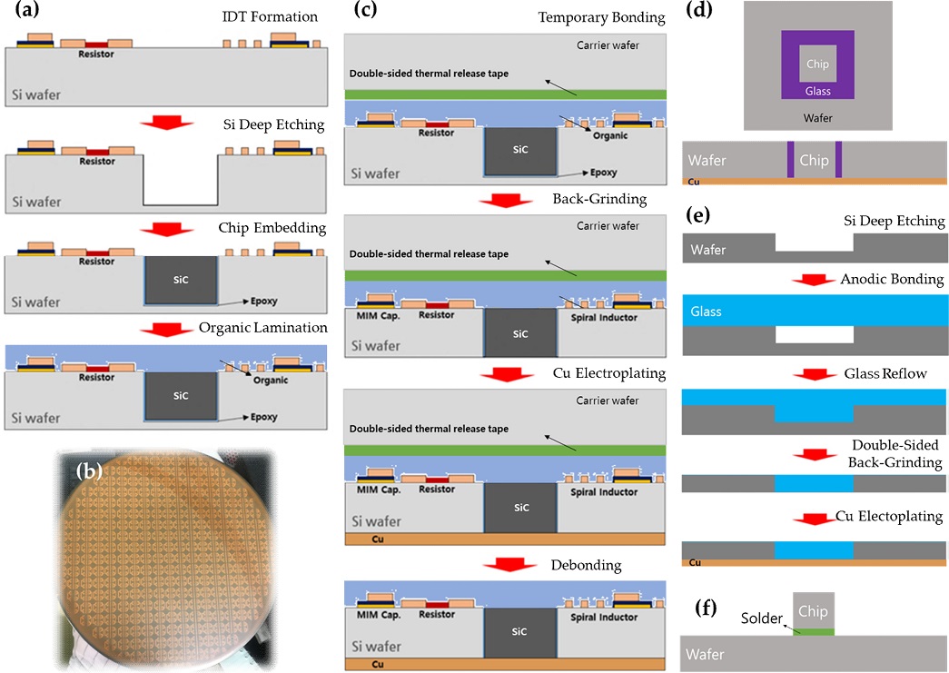
고출력 전자패키지를 구현하기 위한 8인치 기판을 다음과 같이 제작하였다(㈜웨이비스 공급, Fig. 1(a, b)). Deep Si etching 기술인 Bosch process를 통해 interdigital transducer(IDT)가 형성된 8인치 실리콘 웨이퍼에 100 μm 깊이로 칩 크기(~2 mm)의 트렌치를 형성하였다. 그 트렌치 표면을 에폭시로 도포한 후 SiC dummy 칩을 넣고 반도체 패키지의 층간 절연 필름(ajinomoto build-up film, ABF)을 라미네이션 하였다[7].

(a) Process schematic of the embedded IC process with SiC dummy chips for high power applications and (b) photo image of a fabricated 8 inch substrate. (c) Process schematic of the high-power electronic package. (d) Top view and cross sectional schematics, and (e) process schematic of the sample that simulates the high-power electronic package for measuring the heat dissipation effect. (f) Cross sectional schematic of a reference sample that simulates the conventional flip chip package with solders.
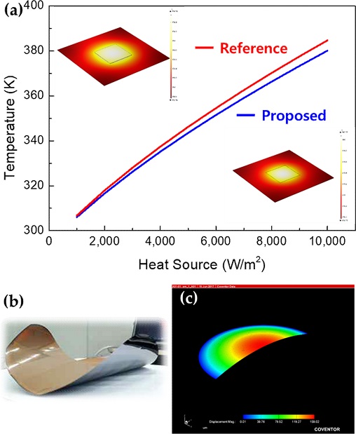
효과적인 방열층은 칩에서 발생한 열을 패키지 기판 끝단의 면으로 빠르게 분산되고, 그 열을 대기 중으로 잘 방사할 수 있어야 한다. Cu의 경우 열전도도가 좋은 반면 적외선 방사율이 낮은 금속으로 알려져 있지만 산화가 될 경우 방사율이 높아지는 것으로 알려져 있다[8]. 본 연구에서는 Fig. 2(a)와 같은 시뮬레이션(COMSOL Multiphysics 5.6)을 통해 기존 플립칩(flip chip) 패키지 (“Reference”, Fig. 1(f) 참조)가 100 oC일 때 제안된 구조(“Proposed”, Fig. 1(d))의 온도는 약 4 oC 낮음을 확인할 수 있었다. 패키지 기판 끝단 표면의 온도는 칩으로부터 전도되어 유입되는 열과 대류 및 복사를 통해 외부로 방출되는 열의 경쟁을 통해 결정될 것인데, 매립된 칩이 적용된 제안된 구조의 경우 열전도성면에서 확실히 유리할 것이기에, 결국 표면의 온도가 낮다는 것은 그만큼 방열 특성이 우수한 것으로 볼 수 있다.

(a) Thermal analysis simulation images and graph of the high-power electronic package (“Proposed”) and a flip chip package (“Reference”), showing that the temperature of the former is 4 oC lower when that of the latter is 100 oC. (b) Photo image of the substrate without Cu electroplating layer on the back side after debonding of the carrier wafer. (c) Image of simulation performed to find the optimal Cu electroplating layer thickness to offset internal stress.
또한 반도체 패키지의 층간 절연 필름 ABF에 의한 compressive stress로 인해 박형화된 웨이퍼의 warpage가 발생하게 되는데(Fig. 2(b)), Cu 도금막의 경우 반대인 tensile stress가 형성되므로 Cu 두께 최적화를 통해 박형화된 웨이퍼 내부의 stress를 상쇄시켜 warpage를 줄일 수 있다. 이에 ABF 필름(~40 μm)의 stress를 stress gauge(FSM500TC, FSM社)를 이용하여 실측한 후, Fig. 2(c)와 같이 시뮬레이션 (CoventorWare)을 통해 최적의 Cu 두께를 구했다. 실측 결과 변이(displacement)는 66.612 μm로 stress는 4.732 MPa였고, 이 경우 Cu도금층이 10 μm일 때 stress가 상쇄되는 것으로 계산되었다.
Fig. 1(c)와 같이 준비한 8인치 기판에 Manual Tape Laminator를 이용하여 상용 양면 열박리 테이프(ST-9595B, 대현에스티社)를 라미레이션한 후 Wafer Bonder(Gemini, EVG社)를 이용하여 캐리어 웨이퍼를 붙이고, Backside Polishing & Thinning 장비(DGP8760, DISCO社)를 이용하여 준비한 기판의 뒷면에 매립된 SiC dummy 칩이 드러날 때까지(기판 두께가 100 μm이 될 때까지) back-grinding을 하였다. 이 후 스퍼터를 이용하여 Cu seed를 증착하고, 10 μm 두께로 Cu를 도금(EP-2000, ENG社)한 후 hot plate에 올려놓고 150 oC의 열을 가해 debonding하였고 표면을 산화시켰다.
2.2 방열 효과 비교 방법
방열 효과를 실험적으로 비교하기 위한 모사 샘플을 다음과 같이 제작하였다(Fig. 1(d, e)). Bosch process를 통해 8인치 실리콘 웨이퍼에 5 mm × 5 mm 사각형 주위로 100 μm 깊이와 폭의 라인 트렌치를 형성하여 실리콘 칩을 모사하였다. 다음으로 8인치 Boro33 유리 웨이퍼를 얹고 400 oC, 1kN 조건으로 anodic bonding (EVG520HE, EV Group社)을 진행한 후 950 oC glass reflow 공정을 통해 트렌치를 유리로 채웠다[9]. 이 후 실리콘 웨이퍼가 드러날 때까지 유리를 back-grinding하고 실리콘 웨이퍼도 두께가 100 μm이 될 때까지(유리로 채워진 트랜치가 드러날 때까지) back-grinding한 뒤 Cu seed 증착 및 도금을 진행하였다.
고출력 전자패키지를 모사한 샘플을 hot plate 위에 있는 칩면적의 Cu 블록 위에 두고 ~100 oC로 온도를 올린 후 열화상 카메라(A305sc, FLIR社)를 이용하여 방열 특성을 측정해 보았다. (반사를 줄이기 위해 캡톤 테이프를 표면에 붙였다.) 방열 효과 비교를 위해 기존 플립칩(flip chip) 패키지를 모사한 샘플, 즉 5 mm × 5 mm 크기의 실리콘 칩을 Vacuum Reflow 장비(SST3150, Palomar社)에서 솔더(SnAg solder freeform, Indium Corporation of America社)로 박형한 실리콘 웨이퍼에 본딩한 샘플(Fig. 1(f))도 함께 측정하였다.
3. 결과 및 고찰
3.1 고출력 전자패키지 제작
임시 접합용 테이프로는 크게 UV 테이프와 열박리 테이프가 있으며, 열박리 테이프는 UV테이프에 비해 소자에 150 oC의 열을 주는 단점은 있지만, 잔류 점착력이 거의 사라져, 본 연구와 같이 약간의 힘에도 파손될 위험성이 높은 박형화된 대면적 웨이퍼에 적합하다.
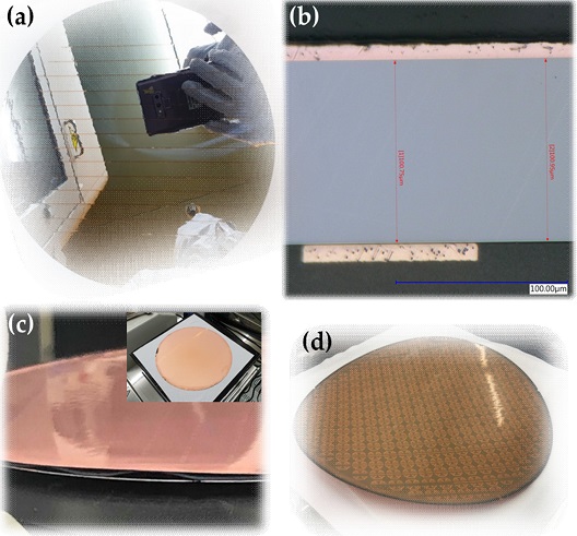
Fig. 3(a)는 양면 열박리 테이프 기반 임시 접합 공정을 이용한 back-grinding을 통해 8인치 실리콘 기판 뒷면에 SiC dummy 칩들이 드러나 있음을 알 수 있다. Fig. 3(b)는 웨이퍼의 단면을 폴리싱(Multiprep, Allied社) 후 관찰한 광학현미경 이미지로, 100 mm 두께로 back-grinding된 모습을 보여준다.

(a) Photo image of the back side of the substrate after back-grinding. (b) Cross sectional optical microscope image of the substrate after the Cu electroplating. (c) Photo image showing the debonding, i.e. the gap between the substrate and the underlying carrier wafer on the hot plate. (d) Photo image of the finished high-power electronic package.
양면 열박리 테이프 기반 임시 접합된 캐리어 웨이퍼를 통해 핸들링은 물론, 다음 공정인 Cu 도금으로 방열층을 형성할 수 있었다. 다만 캐리어 웨이퍼의 debonding 시 박형화된 웨이퍼의 warpage 문제가 발생할 수 있는데, 실제로 Cu 레이어가 없을 경우 Fig. 2(b)와 같이 warpage가 심하게 발생하였다. Warpage가 일어나는 가장 큰 요인은 두꺼운 ABF 필름(~40 μm)에 의한 compressive stress이고, 시뮬레이션을 통해 tensile stress의 Cu 도금막이 상쇄할 수 있는 계산된 두께인 10 μm만큼 Cu를 도금한 후 150 oC hot plate 위에 기판을 두고 살짝 밀어 캐리어 웨이퍼로부터 최종적인 고출력 전자패키지를 debonding 할 수 있었다(Fig. 3(c)).
Fig. 3(d)는 고출력 전자패키지의 최종 모습으로, Fig. 2(b)의 warpage보다는 훨씬 덜하지만 약간의 warpage가 있는데, 이는 ABF의 두께 편차가 심한데서 연유한 것으로 판단된다. 추후 ABF의 두께 편차를 줄이는 공정 개발이 필요할 것으로 보인다.
3.2 모사 기판을 통한 방열 효과 비교
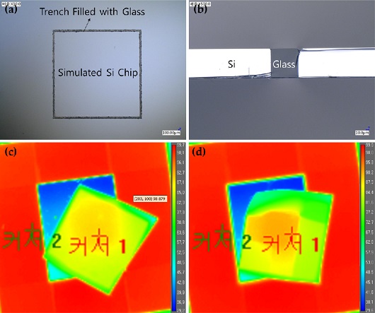
Fig. 4(a)는 고출력 전자패키지를 모사한 샘플의 평면 광학 이미지이고, Fig. 4(b)는 Cross Section Polisher(IB-19520CCP, JEOL社)로 가공한 후의 단면 광학 이미지로, glass reflow를 통해 유리가 100 μm 깊이의 실리콘 트렌치에 잘 채워져 있음을 알 수 있다. 이를 통해 5 mm × 5 mm 크기의 실리콘 칩이 실리콘 기판과 isolation되어 매립된 칩의 모사가 되었다. 다만 트렌치의 엣지부가 약간 깨져 있는데 아마도 액화된 유리의 첨단부가 표면장력에 의해 트렌치 바닥의 귀퉁이를 완전히 채우지 못하고 polishing 시 damage를 입은 것으로 보인다.

(a) Top view and (b) cross sectional optical microscope images of the simulated high-power electronic package. These show that glass was filled with Si trench. Thermal camera images of (c) the simulated high-power electronic package and (d) the simulated typical flip chip package with solders. These show that the proposed high-power electronic package has good heat dissipation characteristics.
Fig. 4(c)와 (d)는 100 oC hot plate 위에 올려놓은 고출력 전자패키지를 모사한 샘플(Fig. 1(d) 참고)과 기존 플립칩 패키지를 모사한 샘플(Fig. 1(f) 참고)의 방열 특성을 열화상 카메라를 이용하여 비교한 결과이다. 각 “커서 1”은 샘플 영역 중 가장 높은 온도를, “커서 2”는 주변 hot plate의 온도를 측정한 위치를 나타낸다. Table 1과 같이 두 측정 모두 hot plate 온도가 ~99 oC로 동일함을 알 수 있고, 시뮬레이션 결과와 유사한 경향으로 고출력 전자패키지를 모사한 샘플의 온도가 플립칩 패키지를 모사한 샘플보다 약 2 oC 낮고, 열이 더 고르게 분산되어 있음을 확인할 수 있다. 이를 통해 고출력 전자패키지의 방열 특성이 기존 플립칩 패키지 대비 우수한 것으로 판단된다.
4. 결 론
본 연구에서는 embedded IC process로 제작된 8인치 기판을 양면 열박리 테이프를 이용하여 캐리어 웨이퍼에 임시 접합한 후 기판를 박형화하고, 박형화된 기판에 Cu 도금으로 방열층을 형성한 후 캐리어 웨이퍼를 박리하여 성공적으로 고출력 전자 패키지를 구현하였다. 제작된 고출력 전자패키지의 방열 효과를 증명하기 위해 고출력 전자패키지와 기존 플립칩 패키지를 모사한 샘플을 제작하고 열화상 카메라로 방열 효과를 비교하였고 고출력 전자패키지의 방열이 기존 플립칩 대비 우수함을 보였다. 본 연구를 통해 개발된 기술은 향후 고방열을 위한 고출력 전자패키지의 상용화에 기여할 것으로 판단된다.
Acknowledgments
Embedded IC process를 이용하여 8인치 기판을 공급해 주신 ㈜웨이비스社에 감사를 드립니다. 이 논문은 한국산업기술평가관리원의 디스플레이혁신 공정플랫폼구축사업(20006476)의 지원으로 수행되었습니다.
REFERENCES
- B.-D. Han, J. W. Ko, and Y. K. Kim, “Heat dissipation materials technology for high-power electronic package”, Proc. of the KIIEE, Vol. 30, No. 1, pp. 39-47, 2016.
- H. K. Lim and J. H. Kim, “Development and technology trends of heat dissipation composite materials for electronic materials”, News Inf. Chem. Eng., Vol. 29, No. 5, pp. 554-560, 2011.
-
J. M. Yook, D. Kim, and J. C. Kim, “Small and Low-profile GaN Hybrid-IC LNA using Embedded-IC Process in Silicon”, IEEE MTT-S Int. Microw. Workshop Series Adv. Mater. Process., pp. 17488731(1)- 17488731(3), Pavia, Italy, 2017.
[https://doi.org/10.1109/IMWS-AMP.2017.8247402]

- H. Lee, “Semiconductor package technology trends,” The Magazine of the IEIE, Vol. 40, No. 12, pp. 1155-1161, 2013.
- S. H. Choa, B. H. Ko, and H. S. Lee, “Recent Trends of MEMS Packaging and Bonding Technology,” J. Microelectron. Packag. Soc., Vol. 24, No. 4, pp. 9-17, 2017.
- S. W. Lee, C. H. Park, J. W. Park, D. H. Lim, H. J. Kim, J. Y. Song, J. H. Lee, “Temporary Bonding and Debonding Adhesives for 3D Multichip Packaging”, Polym. Sci. Technol., Vol. 24, No. 3, pp. 277-284, 2013.
-
D. Kim, J. M. Yook, S. J. An, S. R. Kim, J. G. Yook and J. C. Kim, “A Compact and Low-profile GaN Power Amplifier Using Interposer-based MMIC Technology,” IEEE 16th Electron. Packag. Technol. Conf., pp. 672-675, 2014.
[https://doi.org/10.1109/EPTC.2014.7028416]

-
J. Park, D. Kim, H. Kim, J. Lee, and W. Chung, “Thermal Radiative Copper Oxide Layer for Enhancing Heat Dissipation of Metal Surface”, Nanomaterials, Vol. 11, No. 11, pp. 2819(1)-2819(10), 2021.
[https://doi.org/10.3390/nano11112819]

-
Y. Kim and K. Chun, “Plano-Convex Lens Fabrication for Distance Sensor based on Single Vision”, Int. Conf. Electron. Inform. Commun., pp. 18653695(1)-18653695(3), Auckland, New Zealand, 2019.
[https://doi.org/10.23919/ELINFOCOM.2019.8706497]

