가열 전극 통합 채널 공진기의 진공 환경 구동에 의한 열물성 측정의 민감도 향상
This is an Open Access article distributed under the terms of the Creative Commons Attribution Non-Commercial License(https://creativecommons.org/licenses/by-nc/3.0/) which permits unrestricted non-commercial use, distribution, and reproduction in any medium, provided the original work is properly cited.
Abstract
Microscale thermophysical property measurements of liquids have been developed considering the increasing interest in the thermal management of cooling systems and energy storage/transportation systems. To accurately predict the heat transfer performance, information on the thermal conductivity, heat capacity, and density is required. However, a simultaneous analysis of the thermophysical properties of small-volume liquids has rarely been considered. Recently, we proposed a new methodology to simultaneously analyze the aforementioned three intrinsic properties using heater-integrated fluidic resonators (HFRs) in an atmospheric pressure environment comprising a microchannel, resistive heater/thermometer, and mechanical resonator. Typically, the thermal conductivity and volumetric heat capacity are measured based on a temperature response resulting from heating using a resistive thermometer, and the specific heat capacity can be obtained from the volumetric heat capacity by using a resonance densitometer. In this study, we analyze methods to improve the thermophysical property measurement performance using HFRs, focusing on the effect of the ambience around the sensor. The analytical method is validated using a numerical analysis, whose results agree well with preliminary experimental results. In a vacuum environment, the thermal conductivity measurement performance is enhanced, except for the thermal conductivity range of most gases, and the sensitivity of the specific heat capacity measurement is enhanced owing to an increase in the time constant.
Keywords:
Channel resonator, Heat capacity, Simultaneous measurements, Thermal conductivity, Thermophysical properties1. 서 론
액상 시료의 열물성은 전자 소자의 방열과 같은 열관리[1] 및 에너지 저장 시스템[2]이나 광파를 이용한 온열 치료 등 다양한 분야에서 필요한 정보이다. 최근에는 랩온어칩 기술의 개발과 함께 MEMS 공정으로 구현된 유체 채널 통합 센서로 열물성을 측정하려는 연구들이 보고되었다[3-5]. 열전도도 센서의 경우 가장 대표적인 것은 측정 시료를 사이에 두고 가열부와 측정부로 구성하는 방식이며[6], 그 외에도 흘러가는 혼합 유체에서 각 시료의 열전도도에 따라 유체 내에 변화하는 가열 저항의 온도를 측정하는 방식[7, 8], 혹은 가열 주파수를 다르게 할 때 그 세 배 크기의 주파수로 진동하는 온도의 진폭으로 열전도도를 예측할 수 있는 3-오메가 방식[9, 10] 등 다양한 방법들이 널리 응용되고 있다. 비열 센서의 경우에는 온도 측정 센서가 가열이 가능한 마이크로 챔버 시스템 내에 위치하면서 일정 온도를 유지하기 위한 전력 혹은 에너지를 분석하는 방식[11]이 가장 일반적이다. 하지만 시료의 열전달 성능 예측에는 열전도도, 비열을 모두 알아야 하는데, 동시에 이와 같은 열물성을 측정하는 것은 불가능하였으며 따라서 시간에 따라 편차가 발생하는 샘플과 같은 경우 혹은 시료의 오염/유실 등으로 센서 간 샘플의 이동 등으로 인한 오차가 발생할 여지가 크다. 또한, 대부분 PDMS/유리 기반의 채널과 센서를 통합하면서 측정 샘플의 부피가 수십 나노 리터 (nL) 이상으로 제한되었으며, 기존의 부피가 큰 측정 장비들에 비해 낮은 정확도를 가지는 단점이 있었다.
한편, 미소량 유체를 이용하여 액체 자체의 밀도나 액체 내에 부유하는 마이크로/나노 입자 및 세포의 질량을 재기 위해 내부에 채널이 있는 공진기가 사용되었다[12, 13]. 대부분의 연구는 생물학 및 의학 분야의 응용 방안[14]에 중점을 두었기 때문에 온도의 변조보다는 일정한 온도의 유지에 더 초점이 맞추어져 있었다. 광열 방식[15]을 이용하거나 전체 시스템의 가열[16, 17]을 이용하여 온도를 변조시킨 몇 가지 연구가 발표된 바 있지만, 정량적인 가열 및 온도의 제어가 어려웠고, 반응 속도가 느리다는 단점이 있었다. 이러한 문제점으로 빠르고 정량적인 가열을 위한 온칩 가열 소자의 통합 및 저항 측정 방식을 이용한 센서 및 실험 플랫폼이 최근 개발된 바 있다[18].
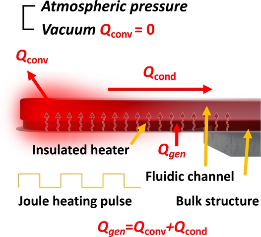
가열 소자 통합 채널 공진기는 수십 피코 리터 (pL) 액상 시료의 열전도도, 비열, 밀도를 동시에 측정할 수 있으며, 온도에 대한 반복적인 응답을 얻음으로써 기존의 MEMS 공정 기반 센서들에 비해 개선된 정확도를 갖는 것을 증명된 실험 플랫폼이다. 본 연구에서는 가열 소자 통합 채널 공진기[18]를 이용하여 열물성 측정 성능에 영향을 미치는 요소를 분석하고 개선시키는 방법에 대해 유한요소해석법을 이용하여 논의하고자 한다. 그 중 센서를 진공 환경에 위치하였을 때 대기로의 열손실을 최소화함으로써 측정 성능이 개선될 수 있을 것이라는 가정을 하였으며, 이를 검증하기 위해 유한요소해석에서 경계조건으로 대류 열전달 계수를 변화시킴으로써 일반적인 대기 환경과 비교하여 진공에서의 열물성 측정의 장점을 분석하였다 (Fig. 1).
2. 연구 방법
2.1 열물성 측정의 원리
밀도 측정을 위해 캔틸레버 형태로 구성된 채널 공진기는 가열 소자를 통합하여 줄히팅으로 온도를 증가시킬 수 있고, 동시에 소자의 저항을 읽음으로써 온도를 측정할 수 있다. 가열 소자는 실리콘 질화물층으로 유체가 흐를 수 있는 채널과는 절연이 되어있다. 이때, 일정 전력을 펄스 형태로 주었을 때 액상 시료의 열물성에 따라 채널 공진기의 온도 응답이 달라진다 (Fig. 2a). 온도 응답을 결정짓는 열물성은 열저항과 열용량을 기준으로 생각할 수 있다. 먼저, 열저항 (thermal resistance, Rth)의 경우 전기 저항을 정의하는 Ohm’s law (R=V/I) 와 대응되는 개념으로 온도 증가량 (ΔT)을 열전달량 (Q)으로 나눈 것 (Rth = ΔT/Q)으로 정의할 수 있으며, 열전도도 (그림에서 k) 로 표현된다[6,8]. 열용량 (Cth)의 경우 온도 변화의 시간 상수 (τ)를 고려하였을 때, Cth = Rth/τ 로 정의되며, 밀도, 비열 (그림에서 cp) 로 표현된다[15].
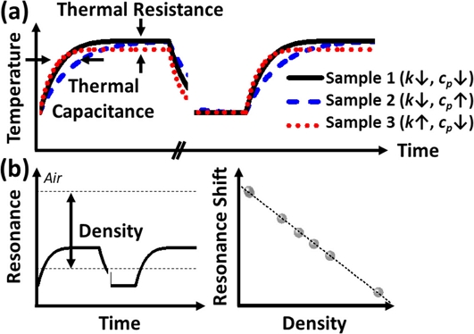
Conceptual illustration of (a) thermophysical properties of three samples with different thermal conductivity and specific heat capacity and (b) density measurements of the various liquid samples inside HFR with real-time temperature and real-time resonance frequency monitoring, respectively.
열전도도가 높은 경우 정상 상태의 온도가 낮게 형성되며, 큰 열용량의 경우 채널 공진기가 정상 상태에 도달하는 데에 걸리는 시간이 오래 걸리게 된다. 한편 열용량은 밀도와 비열의 곱으로 나타낼 수 있으며, 이미 많이 알려져 있는 채널 공진기의 공진주파수-밀도 관계[19]를 이용하면 비열을 독립적으로 추출할 수 있다. 실시간 온도 응답과 동시에 계측한 공진 주파수 응답을 이용하여, 평균 온도에서의 밀도를 예측하면 온도가 변화하는 상황에서도 더 정확한 분석이 가능하다 (Fig. 2b). 본 측정법에서는 측정 오차를 줄이기 위해 전력 펄스를 여러 번 반복하여 각 펄스에 대한 물성치 값을 획득할 수 있으며, 동시간에 동일한 샘플로 열전도도, 비열, 밀도를 획득함으로써 측정 결과에 여러 변수가 함께 작용하는 경우에도 오차를 최소화할 수 있다.
2.2 열물성 측정의 유한요소해석
앞에서 설명한 분석 방법의 실효성을 보기 위해 유한요소해석 모델 (COMSOL Multiphysics, Heat transfer module) 을 만들고 일정 전력을 주었을 때의 온도 응답을 확인하고자 하였다. 모델의 기하 구조는 Fig. 3에 나타나 있다. 실리콘 웨이퍼 위에 실리콘 질화물층 (Si3N4, 100 nm) 이 절연체이자 200 μm 길이의 캔틸레버의 구조를 유지하는 역할을 하며, 질화물층 위에는 불순물 주입 (n-type, phosphorus, 4 × 1020 cm-3) 된 다결정 실리콘 (300 nm) 으로 U자 형태의 가열 전극 (4 × 10⁻⁴ Ω·cm)이 있다. 3 μm높이, 16 μm넓이의 유체 채널을 구현하기 위한 150 nm의 절연층과 채널 벽 (400 nm) 은 다시 실리콘 질화물로 구성하였다. 해석을 위한 mesh는 최소 3-μm의 크기를 갖는 사면체 22031 개로 구성하였다. Mesh 사이즈를 줄이기 위해 실리콘 질화물의 절연층과 불순물 주입된 다결정 실리콘 가열 전극은 thermally thin approximation 을 따르는 thin layer 조건으로 가정하였다. 본 센서의 구조, 제작 과정 및 실험적 특성 파악은 선행연구[18] 에 더 자세하게 설명되어 있다.
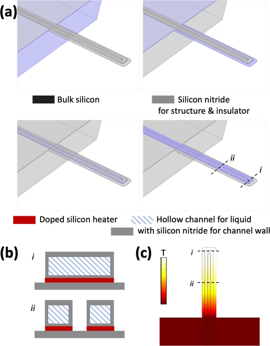
(a) Schematic illustrations of each component in HFR for finite element analysis (FEA). The suspended length of the cantilever, cantilever width, U-shaped fluidic channel width, and channel thickness are 200 μm, 50 μm, 36 μm with two 16 μm turnaround channels, and 3 μm, respectively. (b) Schematic illustrations of cross-section of HFR along the line i and ii in (a). (c) Temperature gradient of HFR during joule heating.
실리콘 웨이퍼의 하단 및 측면 부분은 상온 (298 K) 로 경계조건을 설정하였다. 채널과 웨이퍼 상단은 대류 열전달 경계 조건을 주었다. 열물성 측정 시에는 채널 내부의 길이 방향 열전도 특성을 이용하기 때문에, 측정 환경을 진공으로 구성하여(h=0 W/m2-K) 채널 주변의 대류 열손실 (h=1000 W/m2-K [20])을 줄이면 열물성 측정의 성능을 크게 증가시킬 수 있을 것으로 예상하였다. 줄 (Joule) 가열 전극은 진공 환경의 경우 3 mW의 일정한 전력이 생성되도록 하였으며, 대기압 환경의 경우 용이한 비교를 위해 진공 상태의 공기가 채워진 채널의 정상 상태 온도에 맞추어 7.9 mW 를 인가했다.
열전도도 측정은 정상 상태 (steady-state) 온도에 기인하고, 열용량의 측정은 정상 상태에 도달하는 데에 걸리는 시간과 열전도도에도 기인한다. 이전 실험 결과로부터 실리콘 질화물 채널 내부에 공기로만 채워져 있을 때에 가열된 구조물의 가열 시간 상수는 대략 1 ms 인 것을 알 수 있었다. 이에 유한요소해석에서는 실리콘 질화물 채널 내부가 여러 물성치를 갖는 액체로 채워져 있을 때, 전력이 인가되었을 때를 기점으로 총 40-ms 의 시간 동안 1-ms 시간 간격으로 온도의 과도 응답 (transient response)을 추출하였다. 이때 실질적으로 계측하는 온도는 저항 열측정 방식 (resistive thermometry) 을 사용하여 나온 대푯값이기 때문에 가열 전극의 길이방향 온도 평균으로 대표 온도를 규정하였다.
온도의 응답은 지수적 감쇠 함수 (exponential decay, (T0-Tss)×exp(-t/τ)+Tss) 를 이용하여 곡선 접합하였다 (T0: 초기 온도, t: 시간 (변수), τ: 시간 상수, Tss: 정상 상태 온도). 여기에서 Tss는 독립적으로 열전도도와의 관계 도출에 사용되며, τ/(T0-Tss) 는 열용량과의 관계 도출에 사용된다.
3. 결과 및 고찰
3.1 열전도도에 따른 해석 결과 비교
Fig. 4a는 일정 전력을 주었을 때 열용량을 고정하고 다양한 열전도도에 따른 온도의 과도응답을 나타내는 유한요소해석 결과이다. 대기 환경인 경우 (h=1000 W/m2-K) 진공 환경보다 (h=0 W/m2-K) 정상상태 온도의 변화 폭이 더 큰 것을 확인할 수 있다. 정상 상태의 온도를 열전도도의 함수로 나타낸 결과는 Fig. 4b 에 나타나 있다. 진공 환경에서는 전반적인 열전도도 범위에서 민감도가 동일하게 유지되는 것에 비해, 대기 환경에서는 대략 0.1 W/m-K 이하 (주로 기체 범위) 에서 민감도가 높고 점차 감소하는 양상을 보이는 것을 확인할 수 있다. 진공 환경에서는 0인 대류 열전달 계수로 인해 모든 열전달이 고체 캔틸레버 구조와 유체를 통해서만 이루어지기 때문에 전반적인 열전도도의 민감도가 일정하게 유지되는 것이 합리적이다. 열전도도의 선형 동적 범위로 비교하였을 때, 진공 환경이 대기 환경보다 약 100배 높다. 일반 대기 환경에서 열물성 측정의 가능성을 확인하였던 선행 연구[20]를 참조하면, 레퍼런스 측정값과 잘 일치하는 낮은 열전도도 범위에 비해 (~0.18 W/m-K) 높은 열전도도 범위에서 (~0.6 W/m-K) 열전도도 측정의 오차율이 높아졌었는데, 높은 열전도도 범위에서도 민감도를 유지하는 진공 측정을 구현한다면 이러한 상황에 대해 오차율이 작아질 것으로 예상한다. 하지만 흥미로운 점은, 대기 환경에서는 낮은 열전도도 범위에서 진공에 비해 열전도도의 약 50배 더 높은 기울기를 갖는 것을 확인하였다.
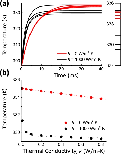
(a) FEA results showing average temperature change of the HFR filled with liquids with different thermal conductivity ranging from 0.01 to 0.8 W/m-K in atmospheric (h=1000 W/m2-K, black) and vacuum (h=0 W/m2-K, red) pressures under a pulse heating. (b) Steady-state average temperature change (ΔT) as a function of liquid thermal conductivity (k).
3.2 열용량에 따른 해석 결과 비교
Fig. 5a 는 일정 전력을 주었을 때 열전도도를 고정하고 다양한 열용량에 따른 온도의 과도 응답과 시간 상수 도출을 위한 함수 피팅을 나타낸다. 대류 열손실이 없는 진공에서 온도 응답이 더 느린 것을 확인할 수 있으며, 피팅 결과로부터 시간 상수가 대략 2배 정도 증가함을 알 수 있었다. 이는 열용량에 대한 시간 상수와 정상상태 온도 통합 변수의 감도가 마찬가지로 2배 증가하는 것을 의미한다. 시간 상수가 증가하기 때문에 측정시간을 함께 늘려주는 것이 필요하다. 하지만 본 측정 시스템이 정상상태에 도달하는 데에는 대기압인 경우 대략 20 ms, 진공인 경우 40 ms 의 시간이 소요되기 때문에 (가장 높은 열용량 기준), 두 경우에서 모두 측정 오차를 줄이기 위해 수백 회 반복하더라도 수 초 이내의 측정이 가능하다. 흥미로운 점은, 시간 상수와 정상상태 온도 통합 변수는 열용량에 대해 상당히 선형적으로 변화한다는 점인데, 본 논문의 컨셉과는 반대로 이 민감도의 증가량을 해석적 결과와 실험적 결과를 비교하여 열전달계수를 예측하는 연구에도 응용이 가능하다. 열전달계수는 특성 길이 (characteristic dimension) 에도 영향을 받기 때문에[20], 마이크로 열전달 분석을 위한 플랫폼에서 동일한 특성 길이를 갖는 가열 소자 통합 채널 센서를 함께 제작한다면 열전달 계수의 예측이 가능할 것이다.
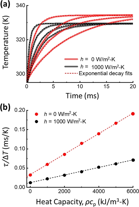
(a) FEA results showing average temperature change of the HFR filled with liquids with different volumetric heat capacity ranging from 100 to 6000 kJ/m3-K. To extract time constant (τ), exponential decay fit is used (dashed lines) for each FEA result (semi-transparent lines). (b) Time constant as a function of volumetric heat capacity (ρcp).
요약하면, 열전도도가 높은 유체에 대해 (대부분의 액체 범위) 높은 감도를 위해서는 대류 손실이 없는 진공 환경이 유리하다. 진공 환경에서는 열전도도/열용량의 범위에 관계없이 열용량의 높은 감도를 제공하기 때문이다. 반면 열전도도가 낮은 기체로 측정 대상을 한정한다면 대기압 상태로 센서 환경을 유지하였을 때 기체의 열전도도에 대해 더 높은 민감도를 가질 수 있다.
4. 결 론
본 연구에서는 가열 소자 통합 채널 공진기를 이용한 소량 액상 시료의 열물성을 측정 기술의 성능을 개선시키는 방법을 소개한다. 먼저 유한요소해석을 이용하여 실험적으로 확립하였던 열물성 측정 기술의 분석 방식이 해석적으로도 잘 맞는 것을 확인하였으며, 해석 모델을 사용하여 열물성 측정의 성능에 영향을 미치는 요소 중 하나인 센서 주변 환경에 대한 영향을 분석하였다. 대류 열전달 계수가 최소화된 진공 환경에서의 측정이 성능이 개선될 것이라고 예상하였고, 해석 모델을 이용하여 상압의 대기 환경일 때의 측정 예상 결과와 비교해보니 열전도도와 비열 측정에 모두 이점이 있는 것을 확인하였다. 또한, 통상 기체의 열전도도의 범위에 해당하는 낮은 열전도도 영역에서는 오히려 대기 환경일 때가 더 민감도가 좋을 수도 있다는 다소 비직관적인 결과도 확인하였다.
Acknowledgments
본 연구는 2022년도 과학기술정보통신부의 재원으로 한국연구재단 (NRF-2020R1A2C3004885, 2020R1A4A2002728) 및 산업통상자원부의 재원으로 산업기술평가관리원 (KEIT-00144157)의 지원을 받아 수행되었다.
REFERENCES
-
M. Ghanbarpour, E. Bitaraf Haghigi, and R. Khodabandeh, “Thermal properties and rheological behavior of water based Al2O3 nanofluid as a heat transfer fluid”, Exp. Therm. Fluid. Sci., Vol. 53, pp. 227-235, 2014.
[https://doi.org/10.1016/j.expthermflusci.2013.12.013]

-
D. Shin and D. Banerjee, “Enhanced thermal properties of SiO2 nanocomposite for solar thermal energy storage applications”, Int. J. Heat. Mass. Transf., Vol. 84, pp. 898-902, 2015.
[https://doi.org/10.1016/j.ijheatmasstransfer.2015.01.100]

-
G. Paul, M. Chopkar, I. Manna, and P. K. Das, “Techniques for measuring the thermal conductivity of nanofluids: A review”, Renew. Sustain. Energy Rev., Vol. 14, No. 7, pp. 1913-1924, 2010.
[https://doi.org/10.1016/j.rser.2010.03.017]

-
S. R. Choi and D. Kim, “Real-time thermal characterization of 12 nl fluid samples in a microchannel”, Rev. Sci. Instrum., Vol. 79, No. 6, p. 064901, 2008.
[https://doi.org/10.1063/1.2937180]

-
B. K. Park, N. Yi, J. Park, and D. Kim, “Note: Development of a microfabricated sensor to measure thermal conductivity of picoliter scale liquid samples”, Rev. Sci. Instrum., Vol. 83, No. 10, p. 106102, 2012.
[https://doi.org/10.1063/1.4757400]

-
R. Shrestha, K. M. Lee, W. S. Chang, D. S. Kim, G. H. Rhee, and T. Y. Choi, “Steady heat conduction-based thermal conductivity measurement of single walled carbon nanotubes thin film using a micropipette thermal sensor”, Rev. Sci. Instrum., Vol. 84, No. 3, p. 034901, 2013.
[https://doi.org/10.1063/1.4792841]

-
B. Zhao, F. Feng, B. Tian, Z. Yu, and X. Li, “Micro thermal conductivity detector based on SOI substrate with low detection limit”, Sens. Actuators B Chem., Vol. 308, p. 127682, 2020.
[https://doi.org/10.1016/j.snb.2020.127682]

-
A. Mahdavifar, M. Navaei, P. J. Hesketh, M. Findlay, J. R. Stetter, and G. W. Hunter, “Transient thermal response of micro-thermal conductivity detector (μTCD) for the identification of gas mixtures: An ultra-fast and low power method”, Microsyst. Nanoeng., Vol. 1, No. 1, p. 15025, 2015.
[https://doi.org/10.1038/micronano.2015.25]

-
S. Gauthier, A. Giani, and P. Combette, “Gas thermal conductivity measurement using the three-omega method”, Sens. Actuators A Phys., Vol. 195, pp. 50-55, 2013.
[https://doi.org/10.1016/j.sna.2012.12.032]

-
D. G. Cahill, “Thermal conductivity measurement from 30 to 750 K: the 3ω method”, Rev. Sci. Instrum., Vol. 61, No. 2, pp. 802-808, 1990.
[https://doi.org/10.1063/1.1141498]

-
W. Lee, W. Fon, B. W. Axelrod, and M. L. Roukes, “High-sensitivity microfluidic calorimeters for biological and chemical applications”, Proc. Natl. Acad. Sci., Vol. 106, No. 36, pp. 15225-15230, 2009.
[https://doi.org/10.1073/pnas.0901447106]

-
T. P. Burg, M. Godin, S. M. Knudsen, W. Shen, G. Carlson, J. S. Foster, K. Babcock, and S. R. Manalis, “Weighing of biomolecules, single cells and single nanoparticles in fluid”, Nature, Vol. 446, No. 7139, pp. 1066-1069, 2007.
[https://doi.org/10.1038/nature05741]

-
J. Ko, D. Lee, B. J. Lee, S. K. Kauh, and J. Lee, “Micropipette resonator enabling targeted aspiration and mass measurement of single particles and cells”, ACS Sens., Vol. 4, No. 12, pp. 3275-3282, 2019.
[https://doi.org/10.1021/acssensors.9b01843]

-
J. Ko, J. Jeong, S. Son, and J. Lee, “Cellular and biomolecular detection based on suspended microchannel resonators”, Biomed. Eng. Lett., Vol. 11, No. 4, pp. 367-382, 2021
[https://doi.org/10.1007/s13534-021-00207-7]

-
M. F. Khan, N. Miriyala, J. Lee, M. Hassanpourfard, A. Kumar, and T. Thundat, “Heat capacity measurements of sub-nanoliter volumes of liquids using bimaterial microchannel cantilevers”, Appl Phys. Lett., Vol. 108, No. 21, p. 211906, 2016.
[https://doi.org/10.1063/1.4952614]

-
M. Yun, I. Lee, S. Jeon, and J. Lee, “Facile phase transition measurements for nanogram level liquid samples using suspended microchannel resonators”, IEEE Sens. J., Vol. 14, No. 3, pp. 781-785, 2014.
[https://doi.org/10.1109/JSEN.2013.2287887]

-
I. Lee, K. Park, and J. Lee, “Precision density and volume contraction measurements of ethanol-water binary mixtures using suspended microchannel resonators”, Sens. Actuators A Phys., Vol. 194, pp. 62-66, 2013.
[https://doi.org/10.1016/j.sna.2013.01.046]

-
J. Ko, F. Khan, Y. Nam, B. J. Lee, and J. Lee, “Nanomechanical sensing using heater-integrated fluidic resonators”, Nano Lett., Vol. 22, No. 19, pp. 7768-7775, 2022.
[https://doi.org/10.1021/acs.nanolett.2c01572]

-
P. Enoksson, G. Stemme, and E. Stemme, “Silicon tube structures for a fluid-density sensor”, Sens. Actuators A Phys., Vol. 54, No. 1-3, pp. 558-562, 1996.
[https://doi.org/10.1016/S0924-4247(97)80014-3]

- J. Peirs, D. Reynaerts, and H. van Brussel, “Scale effects and thermal considerations for micro-actuators”, Proc. 1998 IEEE Int. Conf. Robot.Autom., Vol. 2, pp. 1516-1521, 1988.
