Highly Sensitive Stretchable Electronic Skin with Isotropic Wrinkled Conductive Network
This is an Open Access article distributed under the terms of the Creative Commons Attribution Non-Commercial License(https://creativecommons.org/licenses/by-nc/3.0/) which permits unrestricted non-commercial use, distribution, and reproduction in any medium, provided the original work is properly cited.
Abstract
Soft-pressure sensors have numerous applications in soft robotics, biomedical devices, and wearable smart devices. Herein, we present a highly sensitive electronic skin device with an isotropic wrinkled pressure sensor. A conductive ink for soft pressure sensors is produced by a solution process using polydimethylsiloxane (PDMS), poly 3-hexylthiophene (P3HT), carbon black, and chloroform as the solvents. P3HT provides high reproducibility and conductivity by improving the ink dispersibility. The conductivity of the ink is optimized by adjusting the composition of the carbon black and PDMS. Soft lithography is used to fabricate a conductive elastic structure with an isotropic wrinkled structure. Two conductive elastic structures with an isotropic wrinkle structure is stacked to develop a pressure sensor, and it is confirmed that the isotropic wrinkle structure is more sensitive to pressure than when two elastic structures with an anisotropic wrinkle structure are overlapped. Specifically, the pressure sensor fabricated with an isotropic wrinkled structure can detect extremely low pressures (1.25 Pa). Additionally, the sensor has a high sensitivity of 15.547 kpa-1 from 1.25 to 2500 Pa and a linear sensitivity of 5.15 kPa-1 from 2500 Pa to 25 kPa.
Keywords:
Soft pressure sensor, Micro-structure, Tactile sensor, Conductive ink1. INTRODUCTION
Recently, soft-pressure sensors, driven by their diverse potential applications in areas such as wearable devices [1-3], personal health monitoring [4-6], and human–motion interfaces [7], have experienced a notable surge. Pressure detection mechanisms can be categorized into piezoresistive [8,9], piezo-capacitive [10,11], piezoelectric [12,13], and triboelectric [14,15]. Piezoresistive soft-pressure sensors transform the external pressure into a variation in electrical resistance by modifying the contact area between the active layer of the sensor and the electrode. Piezoresistive materials have gained widespread use owing to their numerous advantages, including high sensitivity in the low-pressure range, cost-effectiveness, and simple form factors.
For advanced applications, it is necessary to develop a pressure sensor that can respond with high sensitivity even at low pressures. Along with the development of micro/nanostructure manufacturing technology, several studies have been conducted to improve sensor performance by changing the shape of a composite material in which a conductive material and a polymer are mixed. Specifically, Bao et al. developed an ultrasensitive resistive pressure sensor that could detect a pressure of 0.8 Pa based on a hollow sphere microstructure that was sensitively deformed according to the pressure [16]. Cho demonstrated linear sensitivity in the working range of 1–12 kPa by implementing a hierarchical dome structure [17]. However, because both studies were based on photolithography, the manufacturing process was complex, and difficulties arose in terms of the manufacturing cost and time.
Wrinkle structures can be produced by simple stretching and surface plasma treatment, making them easy to manufacture without photolithography. In addition, wrinkle structures of various shapes can be produced based on the direction and intensity of stretching. In particular, the strategy of stretching in a bidirectional direction can produce isotropic wrinkles, which have the potential to form a linear contact area based on the pressure, owing to their nonuniform morphology.
Herein, we present a highly sensitive pressure sensor with an isotropic wrinkled interface (PSISI), based on a solution process that can be easily fabricated over a large area. Soft lithography is a fast fabrication process that omits photolithography [18]. To fabricate the pressure sensor, the electrical conductivity of the ink was controlled by adjusting the composition ratio of polydimethylsiloxane (PDMS), carbon black, chloroform solution, and poly 3-hexylthiophene (P3HT). Compared with a flat sensor, the PSISI generates an additional contact area based on the pressure even after contact, resulting in a marked change in the electrical conductivity. Specifically, it was confirmed that the PSISI has a higher sensitivity (Sp1 = 15.547 kPa-1, Sp2 = 5.15 kPa-1) compared to that of the flat sensor and can detect pressures as low as 1.25 Pa. Moreover, PSISI showed a linear electrical conductivity increase of up to 25 kPa.
2. EXPERIMENTAL
2.1 Fabrication of conductive ink
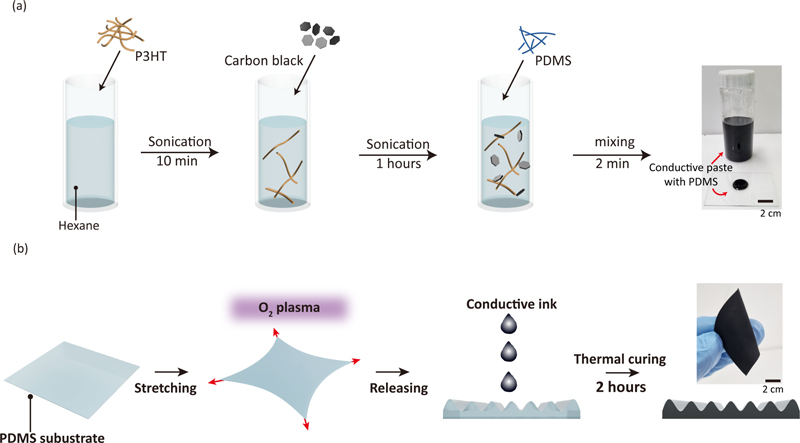
The conductive ink used to manufacture the pressure sensors with an isotropic wrinkle pattern was a composite suspension of PDMS (Dowsil) elastomer and carbon-black nanoparticles (CB, Sigma-Aldrich). PDMS serves as a binder between the conductive CB particles when external stimuli, that can induce sensor deformation, are applied. Poly3hexylthiophene (P3hT, 0.4 g) was sonicated in 20 ml normal hexane for 10 min to improve the dispersibility of conductive carbon. Once dispersion was complete, the solution turned orange. Subsequently, carbon black (8 g) was dded and the mixture was sonicated for 1 h. Thereafter, the mixture was mixed with PDMS (Part A: Part B=9:1) (See Fig. 1(a), Thinky).
2.2 Fabrication of isotropic wrinkled conductive patch
The PDMS elastomer base and curing agent were mixed in a 9:1 ratio. An appropriate amount was poured onto a Si wafer and spin-coated at 500 rpm for 60 s. Once the curing was complete, the spin-coating and curing processes were repeated to obtain an appropriate thickness. The O2 plasma surface treatment was performed with 20% strain applied to each corner of the PDMS. During the process, the degree of hardening of the outermost surface increased, which resulted in an increase in the mechanical modulus. Once the plasma treatment was completed, a wrinkled structure was created by removing the strain owing to the difference in modulus. The surface energy was increased through a self-assembled monolayer (SAM, Trichloro(1H,1H,2H,2H-perfluorooctyl) silane) treatment of the manufactured wrinkle structure. Subsequently, the prepared conductive ink was applied, and the solvent was evaporated at room temperature. The isotropic wrinkled electronic skin was cured in an oven at 80°C for 2 h (Fig. 1(b)).
2.3 Measurement of electrical response
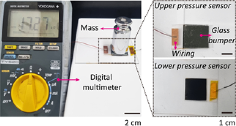
For the sensitivity analysis, an ITO film was used as the electrode. A conductive electronic skin with a wrinkled structure was laminated onto two ITO films. The two ITO films were laminated such that the electronic skin based on the isotropic wrinkle structure was in contact with each other. A glass bumper was placed on the upper pressure sensor. The sensitivity of the sensor was assessed by measuring its electrical resistance, which decreased when pressure was applied to the bumper (see Fig. 2 for details).
3. RESULTS AND DISCUSSIONS
3.1 Interface analysis and dispersion analysis of isotropic wrinkles
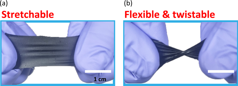
Fig. 3 shows a digital image of the manufactured electronic skin. As shown in Fig. 4(a), the isotropic wrinkled electronic skin was elastic, flexible, and twistable.

digital image of isotropic wrinkled conductive patch (a) Electronic skin showing stretchability, (b) Electronic skin showing flexibility and twistability.

SEM image of wrinkled electronic skin. (a) SEM image of isotropic wrinkled electronic skin, (b) SEM image of anisotropic wrinkled electronic skin, and (c) SEM image of the composite used for fabricating electronic skin.
Fig. 3 presents the results of scanning electron microscope (SEM) analysis. Fig. 4(a) displays the top image of the isotropic wrinkle pattern, and Fig. 4(b) shows the SEM image of the anisotropic wrinkle pattern. Both wrinkle patterns have a wavelength of approximately 30 mm. The wrinkle-patterned structure contained a composite of carbon black and PDMS. As a dispersing agent, P3HT improved the reproducibility and electrical conductivity of the solution. Fig. 4(c) shows that carbon black was well dispersed in the PDMS.
3.2 Sensitivity analysis of isotropic wrinkle pressure sensor
Fig. 5 shows an increase in the electrical response with pressure. The exerted pressure improved the interlocking contact between the upper and lower isotropic wrinkled conductive patches, causing an increase in the current (I) compared to the initial current (I0). Pressure sensitivity (Sp) is characterized by the formula Sp = (ΔI/I0)/ΔP, where ΔI represents the variation in current (I – I0), resulting from the alteration in the applied vertical pressure (ΔP) [19]. In the case of isotropic wrinkles, even though the contact area was initially generated by the bumper, the change in electrical resistance was sensitive to additional pressure. However, when the flat sensors were in contact, the contact area was saturated by increasing the bumper, and the electrical resistance did not change with additional pressure. For anisotropic wrinkles, measurements were performed after contact in both the cross and parallel directions. However, the change in resistance was smaller than that of the contacting isotropic wrinkles. The isotropic wrinkled structure provides the sensor with sensitivity and linearity. The test was performed five times and the average values and error ranges are presented. Unlike other structures, isotropic wrinkled structures exhibit different heights. Therefore, the initial contact area is small compared to those of the other structures, which indicates the possibility of additional contact surfaces based on the pressure (Fig. 6). This ensures higher sensitivity and linearity compared with Fig. 5(b) shows the pressure-dependent electrical conductivity at low pressures. It was confirmed that the pressure sensor with isotropic wrinkles has higher sensitivity than the other structures.

Sensitivity analysis for isotropic wrinkled conductive electronic skin. (a) Electrical conductivity analysis for conductive ink, (b) Sensitivity analysis for pressure sensor from 1.25 Pa to 25 kPa, (c) Sensitivity analysis for pressure sensor from 1.25 Pa to 2500 Pa.
4. CONCLUSIONS
A pressure sensor was fabricated via soft lithography, which can be manufactured in large quantities with large areas and a high density using carbon-based conductive ink. The fabricated stretchable pressure sensor with an isotropic wrinkled structure is capable of high-sensitivity sensing based on a solution process. The conductivity of the ink was optimized by adjusting the ratio of carbon black and PDMS. Additionally, through a comparison with various sensors, such as those with isotropic wrinkles, anisotropic wrinkles, and flats, an isotropic wrinkle structure was deemed to be the optimal structure. The fabricated PSISI exhibited low-pressure sensing of 1.25 Pa and high sensitivity to pressure. A pressure sensor patterned with an isotropic wrinkle structure can be applied to a robot's hand or wearable device.
Acknowledgments
This study was supported by the SKKU Excellence in Research Award Research Fund of the Sungkyunkwan University (2023).
REFERENCES
-
X. Wang, L. Dong, H. Zhang, R. Yu, C. Pan, and Z. L. Wang, “Recent progress in electronic skin”, Adv. Sci., Vol. 2, No. 10, pp. 1500169(1)-1500169(21), 2015.
[https://doi.org/10.1002/advs.201500169]

-
S. Gong, W. Schwalb, Y. Wang, Y. Chen, Y. Tang, J. Si, B. Shirinzadeh, and W. Cheng, “A wearable and highly sensitive pressure sensor with ultrathin gold nanowires”, Nat. Commun., Vol. 5, No. 1, pp. 3132(1)-3132(8), 2014.
[https://doi.org/10.1038/ncomms4132]

-
Y. Guo, M. Zhong, Z. Fang, P. Wan, and G. Yu, “A wearable transient pressure sensor made with MXene nanosheets for sensitive broad-range human–machine interfacing”, Nano lett., Vol. 19, No. 2, pp. 1143-1150, 2019.
[https://doi.org/10.1021/acs.nanolett.8b04514]

-
W. Honda, S. Harada, T. Arie, S. Akita, and K. Takei, “Wearable, human?interactive, health?monitoring, wireless devices fabricated by macroscale printing techniques”, Adv. Funct. Mater., Vol. 24, No. 22, pp. 3299-3304, 2014.
[https://doi.org/10.1002/adfm.201303874]

-
X. Cui, F. Huang, X. Zhang, P. Song, H. Zheng, V. Chevali, H. Wang, and Z. Xu, “Flexible pressure sensors via engineering microstructures for wearable human-machine interaction and health monitoring applications”, Iscience, Vol. 25, No. 4, pp. 104148(1)-104148(24), 2022.
[https://doi.org/10.1016/j.isci.2022.104148]

-
J. Hu, G. Dun, X. Geng, J. Chen, X. M. Wu, and T. L. Ren, “Recent progress in the flexible micro-pressure sensors for wearable health monitoring”, Nanoscale Adv., Vol. 5, pp. 3131-3145, 2023.
[https://doi.org/10.1039/D2NA00866A]

-
M. Zhong, L. Zhang, X. Liu, Y. Zhou, M. Zhang, Y. Wang, L. Yang, and D. Wei, “Wide linear range and highly sensitive flexible pressure sensor based on multistage sensing process for health monitoring and human-machine interfaces”, Chem. Eng. J., Vol. 412, p. 128649, 2021.
[https://doi.org/10.1016/j.cej.2021.128649]

-
J. Park, Y. Lee, J. Hong, M. Ha, Y.-D. Jung, H. Lim, S. Y. Kim, and H. Ko, “Giant tunneling piezoresistance of composite elastomers with interlocked microdome arrays for ultrasensitive and multimodal electronic skins”, ACS Nano, Vol. 8, No. 5, pp. 4689-4697, 2014.
[https://doi.org/10.1021/nn500441k]

-
T. Zhao, T. Li, L. Chen, L. Yuan, X. Li, and J. Zhang, “Highly sensitive flexible piezoresistive pressure sensor developed using biomimetically textured porous materials”, ACS Appl. Mater. Interfaces, Vol. 11, No. 32, pp. 29466-29473, 2019.
[https://doi.org/10.1021/acsami.9b09265]

-
O. Atalay, A. Atalay, J. Gafford, and C. Walsh, “A highly sensitive capacitive?based soft pressure sensor based on a conductive fabric and a microporous dielectric layer”, Adv. Mater. Technol., Vol. 3, No. 1, pp. 1700237(1)-1700237(22), 2018.
[https://doi.org/10.1002/admt.201700237]

-
K. H. Ha, H. Huh, Z. Li, and N. Lu, “Soft capacitive pressure sensors: trends, challenges, and perspectives”, ACS Nano, Vol. 16, No. 3, pp. 3442-3448, 2022.
[https://doi.org/10.1021/acsnano.2c00308]

-
Y. Hu, C. Xu, Y. Zhang, L. Lin, R. L. Snyder, and Z. L. Wang, “A nanogenerator for energy harvesting from a rotating tire and its application as a self?powered pressure/speed sensor”, Adv. Mater., Vol. 23, No. 35, pp. 4068-4071, 2011.
[https://doi.org/10.1002/adma.201102067]

-
J. Luo, L. Zhang, T. Wu, H. Song, and C. Tang, “Flexible piezoelectric pressure sensor with high sensitivity for electronic skin using near-field electrohydrodynamic direct-writing method”, Extreme Mech. Lett., Vol. 48, p. 101279, 2021.
[https://doi.org/10.1016/j.eml.2021.101279]

-
N. Gogurla, B. Roy, J. Y. Park, and S. Kim, “Skin-contact actuated single-electrode protein triboelectric nanogenerator and strain sensor for biomechanical energy harvesting and motion sensing”, Nano Energy, Vol. 62, pp. 674-681, 2019.
[https://doi.org/10.1016/j.nanoen.2019.05.082]

-
T. Jin, Z. Sun, L. Li, Q. Zhang, M. Zhu, Z. Zhang, G. Yuan, T. Chen, Y. Tian, X. Hou, and C. Lee, “Triboelectric nanogenerator sensors for soft robotics aiming at digital twin applications”, Nat. Commun., Vol. 11, pp. 5381(1)-5381(12), 2020.
[https://doi.org/10.1038/s41467-020-19059-3]

-
L. Pan, A. Chortos, G. Yu, Y. Wang, S. Isaacson, R. Allen, Y. Shi, R. Dauskardt, and Z. Bao, “An ultra-sensitive resistive pressure sensor based on hollow-sphere microstructure induced elasticity in conducting polymer film”, Nat. Commun., Vol. 5, No. 1, pp. 3002(1)-3002(8), 2014.
[https://doi.org/10.1038/ncomms4002]

-
G. Y. Bae, S. W. Pak, D. Kim, G. Lee, D. H. Kim, Y. Chung, and K. Cho, “Linearly and highly pressure?sensitive electronic skin based on a bioinspired hierarchical structural array”, Adv. Mater., Vol. 28, No. 26, pp. 5300-5306, 2016.
[https://doi.org/10.1002/adma.201600408]

-
A. Gerami, Y. Alzahid, P. Mostaghimi, N. Kashaninejad, F. Kazemifar, T. Amirian, N. Mosavat, M. E. Warkiani, and R. T. Armstrong, “Microfluidics for porous systems: fabrication, microscopy and applications”, Transp. Porous Media, Vol. 130, pp. 277-304, 2019.
[https://doi.org/10.1007/s11242-018-1202-3]

-
S. Chun, W. Son, H. Kim, S. K. Lim, C. Pang, and C. Choi, “Self-powered pressure-and vibration-sensitive tactile sensors for learning technique-based neural finger skin”, Nano lett., Vol. 19, No. 5, pp. 3305-3312, 2019.
[https://doi.org/10.1021/acs.nanolett.9b00922]


