Dual Differential Magnetic Induction Sensor for Magnetic Communication in Extreme Environments
This is an Open Access article distributed under the terms of the Creative Commons Attribution Non-Commercial License(https://creativecommons.org/licenses/by-nc/3.0/) which permits unrestricted non-commercial use, distribution, and reproduction in any medium, provided the original work is properly cited.
Abstract
This paper presents a novel dual differential magnetic induction (DDMI) sensor designed as a receiving element for magnetic communication in extreme environments, such as underwater and underground conditions. The DDMI sensor, fabricated on a printed circuit board, uses Ni-Zn soft ferrite as a ferromagnetic core, with pickup coils wound around four ferromagnetic cores. The sensor achieved an equivalent magnetic noise spectral density of less than 1 pT/√Hz at 20 kHz, enabling detection of weak magnetic fields for reliable communication. To demonstrate its feasibility, a DDMI sensor-based communication system was implemented and tested using quadrature phase-shift keying modulation in a laboratory setting. Successful demodulation at 20 kHz confirmed the sensor’s potential as a robust solution for magnetic communication in harsh environments.
Keywords:
Dual differential magnetic induction sensor, Magnetic communication, Extreme environment, Media1. INTRODUCTION
Magnetic sensors are becoming increasingly important in wireless sensor networks and are finding widespread applications in various wireless communication technologies [1-5]. Recent advancements have spurred research into using magnetic sensors for communication in challenging environments, such as underwater and underground settings [6-9], where conventional electric fields-based methods struggle to perform reliably [6-9].
One major challenge in such environments is the signal attenuation experienced by electric fields when they traverse media with different dielectric properties, such as air–water or air–ground boundaries. For example, in the case of water, the real part of its complex permittivity is close to 80, which is much higher than the permittivity of air (around 1). The imaginary part of the permittivity relates to the loss characteristics of the media, and these losses are frequency-dependent and relatively larger than those in air. Consequently, electric fields undergo substantial attenuation when crossing air-water boundaries.
In contrast, magnetic fields not affected by the permittivity of the media but rather depend on the permeability. This gives magnetic fields a key advantage: minimum signal attenuation when passing through heterogeneous media like air–water or air–ground boundaries. As a result, magnetic field-based Magnetic induction communication (MIC) offers a promising alternative because magnetic fields, unlike electric fields, can penetrate heterogeneous media (e.g., air, water, and soil) with minimal signal loss. This characteristic makes MIC highly suited for underwater and underground communications, where traditional wireless techniques suffer from limitations such as Doppler effects and multipath fading.
Owing to their unique properties, magnetic fields can pass through boundaries between dissimilar media with little to no distortion, except for materials like nickel, cobalt, and iron, which have significantly different permeabilities. This makes magnetic communication more resilient to environmental conditions, offering a potential solution for connecting wireless networks across challenging cross-boundary environments. Moreover, magnetic communication systems are less sensitive to Doppler effects and multipath fading, which are the major limitations of conventional wireless communication systems. Therefore, magnetic communication is becoming a viable alternative for reliable communication in extreme environments [7-9].
In near-field communication, conventional systems face the challenge of limited communication range. To overcome this limitation, magnetic induction (MI) sensors with high magnetic field to voltage conversion ratios and the ability to detect extremely weak magnetic fields (at the pT/√Hz level) are increasingly being explored as potential receiving elements [9,10].
In previous studies, our research team demonstrated the feasibility of magnetic communication using a differential MI (DMI) sensor and a DMI sensor-based receiver at the laboratory level [3]. In addition, we conducted a magnetic communication link test in a real limestone underground mine using a DMI sensor-based receiver. The results showed that the communication distance could be extended to several tens of meters [11]. Building upon this foundation, this paper presents a novel printed circuit board (PCB)-based dual DMI (DDMI) sensor designed as a receiving element for magnetic communication in extreme environments. The proposed DDMI sensor improves the DMI sensor configuration by enhancing the magnetic voltage conversion ratio (MVCR) and reducing the equivalent magnetic noise spectral density (EMNSD), which are both crucial for increasing the communication range and signal reliability in challenging environments.
To validate the effectiveness of the DDMI sensor as a receiving element for magnetic communication, a laboratory evaluation system was established. The evaluation system included a Helmholtz coil as the transmission antenna, and quadrature phase-shift keying (QPSK) modulation was employed owing to its high data rate and noise resistance. This study demonstrates the potential of the DDMI sensor as a robust and efficient solution for magnetic communication in extreme environments.
2. DESIGN AND RESULTS
2.1 Proposed Sensor Design
The design of the proposed MI sensors is illustrated in Fig. 1. These sensors were developed as receiving elements for magnetic communication systems. The sensors were fabricated on a PCB substrate made of FR4 material, which has a relative permittivity of 4.6. The core material chosen for the sensor was Ni-Zn soft ferrite, which exhibited a relative permeability of 700. An enameled copper wire with a diameter of 0.04 mm was used for the pickup coil.
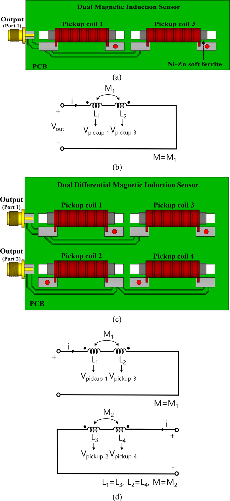
Schematic of the proposed magnetic induction (MI) sensors: (a) dual MI sensor and (b) its electrical circuit; (c) dual differential magnetic induction (DDMI) sensor and (d) its electrical circuit.
The design included two configurations: dual MI sensor and DDMI sensor. The dual MI sensor was developed to compare and verify the performance of the DDMI sensor. Table 1 lists the design parameters of both configurations.
As shown in Fig. 1 (a), the dual MI sensor consists of two pickup coils directly wound around two ferromagnetic cores. The coils are connected in series but in opposite directions, creating a differentially coupled configuration. The first pickup coil (coil 1) and second pickup coil (coil 3) generate opposing currents. This configuration improves sensitivity to magnetic field changes by canceling unwanted noise or interference signals. The corresponding electrical circuit of the dual MI sensor is depicted in Fig. 1 (b). The two pickup coils (coils 1 and 3) can be modeled as two inductances (L1 and L2) with mutual inductance (M). The output voltage of the dual MI sensor is expressed as follows:
| (1) |
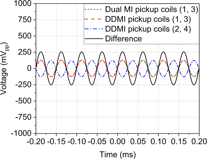
Fig. 1 (c) shows the proposed DDMI sensor, which is an enhancement of the DMI sensor described in [3]. The DDMI sensor incorporates four ferromagnetic cores, each wound with a pickup coil. This configuration is achieved by connecting two DMI sensors in series. The DDMI sensor is connected in a differential manner, where the starting points of pickup coils 1 and 3 are connected to port 1, and the end points of pickup coils 2 and 4 are connected to port 2. Accordingly, the first pickup coils (coils 1 and 3) connected to port 1 and the second pickup coils (coils 2 and 4) connected to port 2 measure the same field but in opposite directions. Therefore, the current directions of the first and second pickup coils are opposite, generating a 180° phase difference between the two sets of coils. This phase difference doubles the magnitude of the induced voltage, significantly improving sensor performance (see Fig. 3).
Fig. 1 (d) illustrates the electrical circuit of the DDMI sensor. The output voltage of this sensor can be calculated using the following equation:
| (2) |
This equation confirms that the DDMI sensor produces an output voltage twice that of the dual MI sensor owing to its improved differential configuration, as indicated in Eq. 2.
2.2 Experimental Results of Sensor
The proposed dual MI and DDMI sensors were experimentally evaluated to validate their performance. The lowest frequency band (19–21 kHz) recommended by the International Telecommunication Union-Radio Communication Sector/Study Groups 1 (ITU-R/SG1) for wireless power transmission was selected for testing. The experiments were conducted at a center frequency of 20 kHz, which corresponds to the external AC magnetic field during the tests.
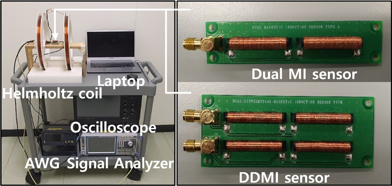
Fig. 2 illustrates the experimental setup for evaluating the proposed MI sensors. A Helmholtz coil was employed as the transmitting antenna to generate the external AC magnetic field. This field was produced by an arbitrary waveform generator (AWG, Keysight, 33500 B) that fed a signal into the Helmholtz coil. The MI sensors received the magnetic flux density generated inside the Helmholtz coil (where the MI sensor was located) and produced a voltage output corresponding to the received magnetic field. The output voltage data from the sensors were collected using a signal analyzer (Rohde & Schwarz, FSV4) and an oscilloscope (Teledyne LeCroy, WaveSurfer 510). A laptop was used to control the interface and data collection processes.
To verify the output voltage characteristics of the dual MI and DDMI sensors, measurements were taken in the time domain, and the results are shown in Fig. 3. When the voltage applied to the Helmholtz coil was 1 Vpp, the converted magnetic flux density was B = 0.1 μT. For the dual MI sensor, the output voltage of pickup coils 1 and 3 was approximately 261 mVpp at 20 kHz. Similarly, the output voltage of pickup coils 1 and 3 for the DDMI sensor measured 261 mVpp. Thus, the output voltage of the dual MI sensor and that of the first pickup coils (coils 1 and 3) of the DDMI sensor were identical. For the second pickup coils (coils 2 and 4) of the DDMI sensor, the measured output voltage was approximately 261 mVpp at 20 kHz. In addition, it was confirmed that a 180° phase difference occurred between the two sets of coils in the DDMI sensor. The difference between the output voltages of the first and second pickup coils was approximately 522 mVpp at 20 kHz. This result aligns with the theoretical predictions from Eq. 2. Therefore, the DDMI sensor demonstrates superior performance by generating twice the output voltage of the dual MI sensor.
Fig. 4 shows the measured induced voltage and MVCR of the DDMI sensor at 20 kHz. A voltage change from 0.001 Vpp to 10 Vpp was applied to the Helmholtz coil, representing a magnetic field strength change of up to 1 μT, as indicated in Fig. 4. The induced voltage (in mVrms), which represents the dynamic range of the DDMI sensor, and the MVCR (in kVrms/T) are displayed in Fig. 4. The MVCR of the DDMI sensor (Fig. 4 (b)) was calculated from the slope of the induced voltage (Fig. 4 (a)). The measured induced voltage and MVCR were 538.4 mVrms and 538 kVrms/T in the first pickup coils and 531.6 mVrms and 532 kVrms/T in second pickup coils of the DDMI sensor, respectively. These results indicate the highly linear characteristics of the induced voltage under a magnetic field of up to 1 × 10⁻⁶ T. In addition, the induced voltage characteristics and MVCR exhibited similar performance characteristics for the first and second pickup coils of the DDMI sensor.
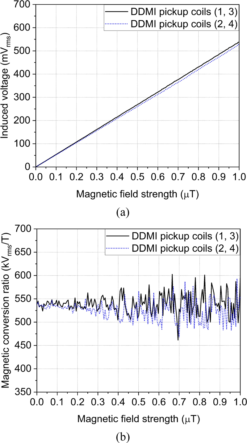
Results of (a) induced voltage and (b) magnetic voltage conversion ratio (MVCR) of the DDMI sensor at 20 kHz.
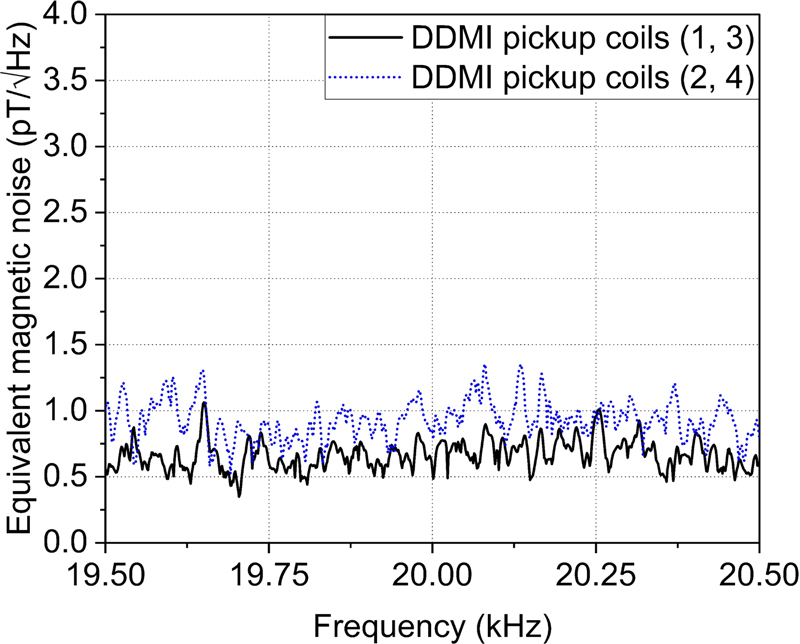
The EMNSD of the DDMI sensor was also evaluated, as shown in Fig. 5. The EMNSD, measured across a frequency bandwidth of 19.5–20.5 kHz, determines the weakest detectable magnetic signals in magnetic communication. The first and second pickup coils of the DDMI sensor showed an EMNSD of 0.55 pT/√Hz and 0.85 pT/√Hz at 20 kHz, respectively. In the DDMI sensor, the overall EMNSD characteristics of the considered frequency bandwidth exhibited similar noise characteristics near 1 pT/√Hz.
Table 2 summarizes the experimental evaluation results for the DDMI sensor and compares them with previously reported MI sensor performance metrics [3]. As indicated, the proposed DDMI sensor demonstrates outstanding characteristics in terms of dynamic range, MVCR, and EMNSD. This makes it a promising candidate as a receiving element for magnetic communication systems, particularly in environments where detecting weak magnetic signals is critical.
2.3 System Configuration
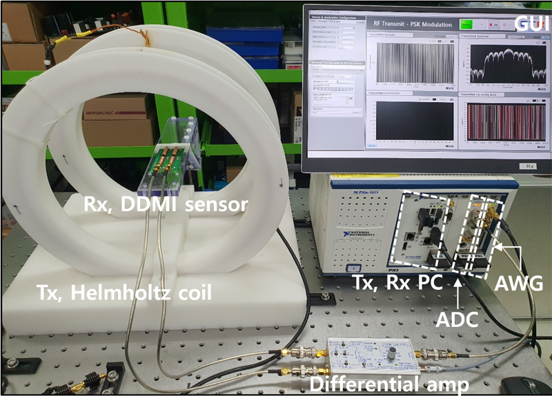
To verify the feasibility of magnetic communication using the proposed DDMI sensor, a complete system was configured and tested in a laboratory setting. The system consisted of a Helmholtz coil as the transmitting antenna and the DDMI sensor as the receiving element, as shown in Fig. 6. The QPSK modulation technique was employed. The transmitted signal had a bandwidth of 1 kHz and a carrier frequency of 20 kHz. A pseudo-random noise sequence code was applied to generate the transmitted signal (see Fig. 7). The modulation signal was generated by the AWG (National Instruments, PXIe-5442) through the graphical user interface (GUI) of the Tx PC (National Instruments, PXIe-8861).
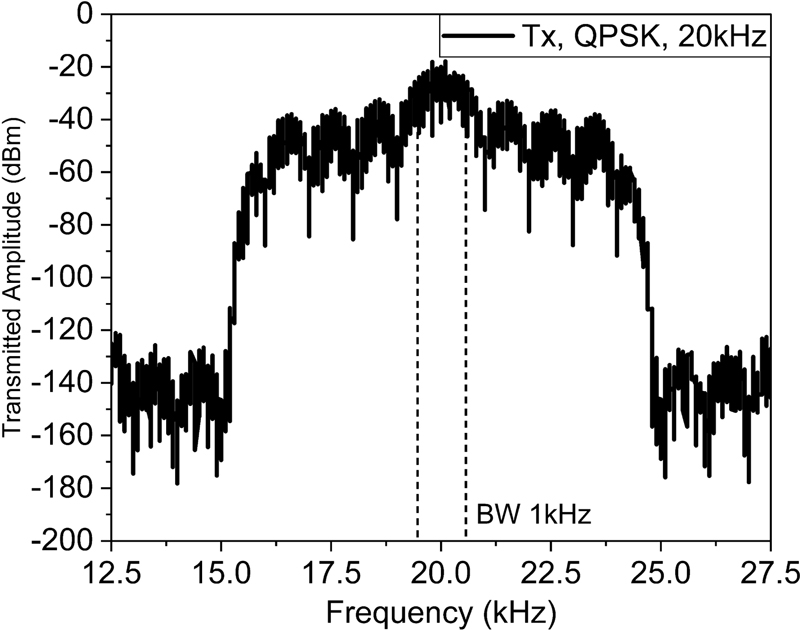
Transmitted analog waveform of a QPSK modulated signal with a 1 kHz bandwidth (BW) at 20 kHz in the frequency domain.
At the receiving end, the DDMI sensor detects the analog QPSK-modulated signal that is sent to the DDMI sensor-based receiver. The receiver system included a differential amplifier with 40 dB gain, an analog-to-digital converter (ADC, National Instruments, PXIe-5122), and an Rx PC (National Instruments, PXIe-8861) configuration. The Rx PC of the DDMI sensor-based receiver decodes the modulation signal and outputs it to the GUI of the Rx PC.
2.4 Results of Magnetic Communication Test
Fig. 7 illustrates the transmitted analog waveform modulated using the QPSK scheme at 20 kHz and a bandwidth of 1 kHz, when 1Vpp signal was applied through the AWG to the Helmholtz coil. The converted magnetic flux density generated by the Helmholtz coil was 0.1 μT.
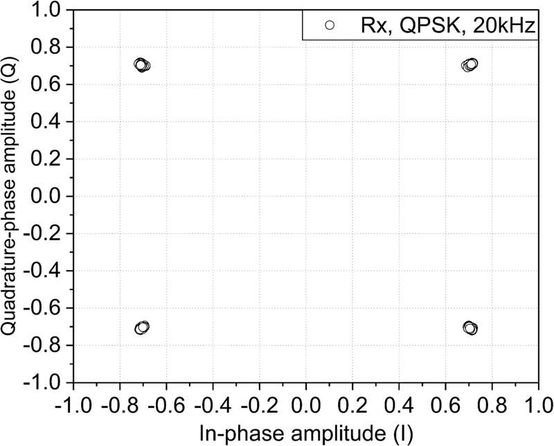
Fig. 8 depicts the constellation results showing the demodulated QPSK signals. The symbols in the constellation plot are located at four points in the in-phase (I) and quadrature-phase (Q) planes of the complex plane. The measured amplitude and phase symbols at each location exhibit a phase difference of 90°. The measured Eb/N0 from the constellation results is 38.8 dB, which indicates strong signal clarity. Because this Eb/N0 value is large, the symbols at each point in the four locations are well concentrated around the expected points, indicating minimal noise interference. Here, Eb is the signal energy associated with the data bit, and N0 is the noise power spectral density within a bandwidth of 1 Hz. Eb/N0 is the normalized signal-to-noise ratio (SNR), known as SNR per bit. Eb/N0 can be expressed as follows:
| (3) |
where C is the total carrier power, N is the total noise power in the bandwidth, Bw is the channel bandwidth in Hz, and Rb is the bit rate in bits per second (bps).
Additionally, the error vector magnitude (EVM) was calculated, which resulted in a root mean square value of 3.68%. This result falls well within 22.4%, which is the standard allowable EVM range for QPSK (as defined by IEEE 801.11ac). The EVM percentage was calculated using the following formula [13,14]:
| (4) |
where S0,n represents the ideal normalized constellation point for the n-th symbol, Sn is the normalized n-th symbol in the stream of measured symbols, and N is the total number of symbols in the constellation. These results demonstrate that the DDMI sensor-based receiver successfully receives the QPSK-modulated signal with minimal data error, confirming its high accuracy and reliability.
Table 3 presents a comparison of the performance metrics for magnetic communication. Compared with existing technologies utilizing magnetic sensors [3,12], the system featuring the proposed DDMI sensor-based receiver shows superior performance, particularly in terms of EVM and Eb/N0. These advantages indicate that it is a promising alternative for magnetic communication in challenging environments such as underwater and underground settings. The results confirm that the DDMI sensor is a well-designed and highly suitable receiving element for magnetic communication applications.
3. CONCLUSION
This paper presents a novel MI sensor called DDMI, which can be used as a receiving element for wireless magnetic communication in extreme environments, including underwater and underground conditions. This DDMI sensor is a ferromagnetic core-based MI sensor with superior magnetic noise characteristics, achieving approximately 1 pT/√Hz. These advantages make it a promising alternative for detecting weak signals and increasing the communication distance in extreme environments. The experimental verification of the feasibility of magnetic communication using QPSK modulation/demodulation at 20 kHz was successful. In future studies, we plan to conduct magnetic communication link tests and analyses in various realworld environments, including air, underwater, and underground media.
Acknowledgments
This work was supported by a grant from the Institute of Information & Communications Technology Planning & Evaluation (IITP) funded by the Korean government (MSIT) (No. 2019-0-00007, Magnetic Field Communication Technology Based on 10pT Class Magnetic Field for Middle and Long Range).
REFERENCES
-
Z. Sun and I. F. Akyildiz, “Magnetic induction communications for wireless underground sensor networks”, IEEE Trans. Antennas Propag., Vol. 58, No. 7, pp. 2426-2435, 2010.
[https://doi.org/10.1109/TAP.2010.2048858]

-
M. Hott and P. A. Hoeher, “Underwater communication employing high-sensitive magnetic field detectors”, IEEE Access, Vol. 8, pp. 177385-177394, 2020
[https://doi.org/10.1109/ACCESS.2020.3026623]

-
J. Y. Kim, H. J. Lee, J. H. Lee, J. H. Oh, and I. K. Cho, “Experimental assessment of a magnetic induction-based receiver for magnetic communication”, IEEE Access, Vol. 10, pp. 110076-110087, 2022.
[https://doi.org/10.1109/ACCESS.2022.3214507]

-
S. Kisseleff, I. F. Akyildiz, and W. H. Gerstacker, “Survey on advances in magnetic induction-based wireless underground sensor networks”, IEEE Internet Things J., Vol. 5, No. 6, pp. 4843-4856, 2018.
[https://doi.org/10.1109/JIOT.2018.2870289]

-
H. J. Lee, J. H. Oh, J. Y. Kim, and I. K. Cho, “Performance analysis of atomic magnetometer and bandwidth-extended loop antenna in in resonant phase-modulated magnetic field communication system”, ETRI J., Vol. 46, No. 4, pp. 727-736, 2024.
[https://doi.org/10.4218/etrij.2023-0156]

-
A. Ranjan, Y. Zhao, H. B. Sahu, and P. Misra, “Opportunities and challenges in health sensing for extreme industrial environment: Perspectives from underground mines”, IEEE Access, Vol. 7, pp. 139181-139195, 2019.
[https://doi.org/10.1109/ACCESS.2019.2941436]

-
M. C. Domingo, “Magnetic induction for underwater wireless communication networks”, IEEE Trans. Antennas Propag., Vol. 60, No. 6, pp. 2929-2939, 2012.
[https://doi.org/10.1109/TAP.2012.2194670]

-
A. R. Silva and M. Moghaddam, “Operating frequency selection for low power magnetic induction-based wireless underground sensor networks”, Proc. of IEEE Sensors Appl. Symp. (SAS), pp. 1-6, Zadar, Croatia, 2015.
[https://doi.org/10.1109/SAS.2015.7133600]

-
J. Y. Kim, H. J. Lee, J. H. Lee, J. H. Oh, and I. K. Cho, “Experimental results of magnetic communication using the giant magnetoimpedance receiver in underwater environments”, J. Electromagn. Eng. Sci., Vol. 23, No. 6, pp. 533-535, 2023.
[https://doi.org/10.26866/jees.2023.6.l.20]

-
A. Grosz and E. Paperno, “Analytical optimization of low-frequency search coil magnetometers”, IEEE Sensors J., Vol. 12, No. 8, pp. 2719-2723, 2012.
[https://doi.org/10.1109/JSEN.2012.2202179]

-
J. Y. Kim, H. J. Lee, J. H. Lee, J. H. Oh, and I. K. Cho, “Magnetic Induction-Based Test-Bed System for Magnetic Communication in Underground Mines”, Proc. of 20th Annu. IEEE Int. Conf. Sens. Commun. Netw. (SECON), pp. 388-389, Madrid, Spain, 2023.
[https://doi.org/10.1109/SECON58729.2023.10287415]

-
K. Kim, S. Ryu, J. Y. Kim, I. K. Cho, H. J. Lee, J. Lee, and S. Ahn, “Giant magnetoimpedance receiver with a double-superheterodyne topology for magnetic communication”, IEEE Access, Vol. 9, pp. 82903-82908, 2021.
[https://doi.org/10.1109/ACCESS.2021.3085603]

-
R. C. Yob, N. Seman, and S. N. A. M. Ghazali, “Error vector magnitude analysis for wideband QPSK and QAM six-port modulator”, Proc. IEEE Int. RF Microw. Conf. (RFM), pp. 149-153, Seremban, Malaysia, 2011.
[https://doi.org/10.1109/RFM.2011.6168717]

-
W. Zhang, A. Hasan, F. M. Ghannouchi, M. Helaoui, Y. Wu, L. Jiao, and Y. Liu, “Homodyne digitally assisted and spurious-free mixer less direct carrier modulator with high carrier leakage suppression”, IEEE Trans. Microw. Theory Tech., Vol. 66, No. 3, pp. 1475-1488, 2018.
[https://doi.org/10.1109/TMTT.2017.2735408]


