Implementation and Performance Evaluation of Wireless Network Using Idle TP Cables on Ship
This is an Open Access article distributed under the terms of the Creative Commons Attribution Non-Commercial License(https://creativecommons.org/licenses/by-nc/3.0/) which permits unrestricted non-commercial use, distribution, and reproduction in any medium, provided the original work is properly cited.
Abstract
This study discusses the utilization of unused pairs of TP cables on a ship to implement a wireless network across the entire vessel. By employing the end-span method with PoE switches, data and power are delivered through the same cables in accordance with IEEE 802.3af/at standards. This approach offers a cost-effective and stable solution for ships without a pre-existing wireless infrastructure. Additionally, it enables centralized monitoring and control of the crew, IP-based systems, and equipment, thus resulting in cost savings and more efficient ship management.
Keywords:
Ship network, SAN (Ship area network), PoE, Wireless network system, Twist pair cables1. INTRODUCTION
As a leading nation in shipbuilding and marine engineering, South Korea implemented proactive measures to continue keeping its leading position in the next-generation shipbuilding market. The government and private sector are working together to enhance South Korea's competitiveness and global reputation in shipbuilding, focusing on three strategic initiatives: securing cutting-edge future technology, advancing manufacturing systems, and refining the legal and institutional infrastructure. Additionally, nine key tasks have been identified: securing a portfolio of future carbon-reducing ship technologies, establishing world-leading technology for autonomous ships, nurturing skilled professionals, promoting international technological cooperation, and enhancing productivity through the digital transformation and smartification of shipyards [1].
The convergence of South Korea’s strong shipbuilding sector with information technology (IT) has fostered the development of the "shipbuilding-IT" convergence industry. Its aim is to create intelligent control systems and integrate the management of ship resources and navigation information, thereby ultimately constructing new-generation digital vessels and securing essential core technologies [2]. Consequently, various network technologies have been introduced for ships. Considering the IoT integration of ship components and network activation of crew members, the need to establish a wireless network environment for ships has grown. However, ships face various challenges owing to their unique maritime environments, which differ from typical land-based environments. Irregular shocks and limited space complicate the network setup, whereas the steel structures of ships hinder the use of wireless communication equipment by blocking wireless signals.
Traditionally, constructing wireless communication networks on ships involves embedding LAN communication cables during the design phase and installing wireless network systems during the construction phase. However, considering that most currently operating ships and those under construction, such as oil tankers and container ships, have an average lifespan of 30 years, utilizing existing infrastructure, such as preinstalled communication or power lines, is a viable alternative to implementing wireless networks across an entire vessel [3].
Twisted pair (TP) cables are laid throughout ships for system equipment power, sensor measurements, and control purposes. To enhance the safety of electrical systems and enable a safe operation during potential failures or disasters, shipyards select TP cables with extra conductors in their electrical design. Utilizing these unused cables enables a quick response for repair and maintenance, provides flexibility in introducing new technologies, and offers expansion opportunities for additional equipment connections.
In this study, a method for implementing a wireless network by utilizing two idle pairs of TP cables between equipment and conducting a data transmission speed experiment to implement a wireless network across an entire large vessel under construction are proposed. PoE switches, omnidirectional antennas equipped with wireless APs, PoE extenders, and other equipment were selected and configured to supply data and power simultaneously over two idle pairs of TP cables, resulting in the development of master and slave boxes.
2. METHOD
2.1 Implementation and Performance Evaluation of Onboard Wireless Network
The Twisted Pair (TP) cables used for ship communications included TTY, TTYC, TTYCY, TTPY, TTPYC, TTPYCY, TTYS, TTYCS, TTYCYS, TTPYS, TTPYCS, and TTPYCYS. Standard cables, starting with TT or TTP, are used for telephone and instrumentation equipment on ships. These cables are 0.75 mm2 thick and have a twisted pair structure, insulation, and shielding, offering high durability and reliability.
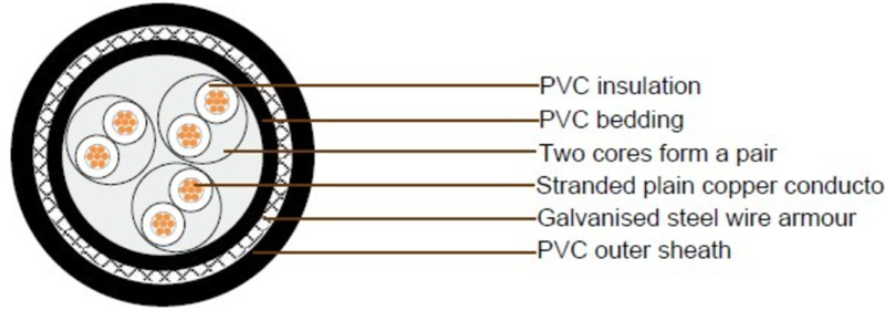
The internal structure of the TTPYCY communication TP cable used in the test ship is illustrated in Fig. 1. Each pair consists of two strands, and the cable can contain between 1 and 48 pairs, depending on the type. The external layer of each pair was wrapped with galvanized steel wire, and PVC fillers and insulators protected the interior of the cable.
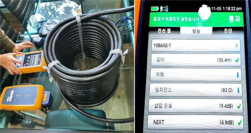
To verify the suitability of the 55-meter ship communication TP cable according to the IEEE 802.3 standard, we used a network cable analyzer (Fluke Networks DSX2-5000) to measure the resistance, impedance, insertion loss, and Near-End Crosstalk according to the 10BASE-T criteria. The results met these standards, as shown in Fig. 2.
Before implementing this system on the test ship, we conducted performance evaluations of the network environments using 55-meter and 150-meter TP cables, which included TCP/IP one-to-one data communication, a PING test, and a network speed test. During the TCP/IP one-to-one communication test, specific data were transmitted 1,000 times in 200-ms intervals, achieving a 100% reception rate. The PING test used a data size of 32 bytes, with a round-trip time of less than 1 ms and a TTL (Time to Live) of 128. All transmitted data were received at a 0% loss rate.
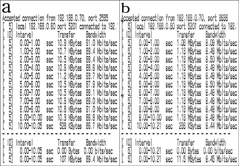
In addition, network speed tests were conducted using 55-meter and 150-meter ship communication TP cables. The network configured with the 55-meter TP cable showed an average speed of 89.4 Mbps, as shown in Fig. 3 (a), while the network configured with the 150-meter TP cable exhibited an average speed of 9.45 Mbps, as shown in Fig. 3 (b). This indicates an approximately 89.4% reduction in network speed.
2.1.2.1 Wireless Network Setup and Testing Equipment
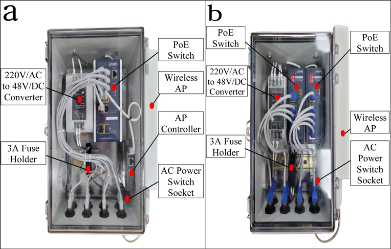
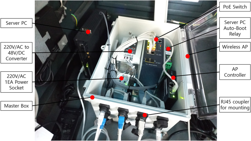
The master box utilizes TP cables distributed across various areas of the ship to expand and manage a PoE-based wireless network. As shown in Fig. 4 (a), the master box contains a 220VAC to 48VDC converter for the PoE power supply, an 8-port PoE switch, and an AP controller, with a wireless AP mounted on the right side of the master box. The slave box uses two pairs of idle TP cables distributed from the master box to implement a wireless network in the installed area and further expands the wireless network by utilizing TP cables distributed to other areas on the ship. As shown in Fig. 4 (b), the slave box contains a 220VAC to 48VDC converter for the PoE power supply, two 4-port PoE switches, and a wireless AP mounted on the right side of the slave box.
The basic PoE power supply method uses the end-span method, which simultaneously transmits data and power over four cables (1/2(+), 3/6(-)). Additionally, the equipment selected and configured to implement and test the onboard wireless network adheres to the IEEE 802.3 and 802.11 standards, ensuring stable and efficient switching and operation between wired and wireless networks. The IEEE 802.11 standard is widely used in wireless networks and supports a wide range of speeds and frequency bands. In large spaces, such as ships, it is crucial to support seamless roaming by installing multiple APs. Therefore, wireless APs using the latest IEEE 802.11ax (Wi-Fi 6) standard were selected to enhance the bandwidth efficiency, enable large-scale device connections, and ensure continuous connections to the same network as users move across different areas on the ship.
2.1.2.2 Server PC and Wireless Network Installations
The master box and server PC were installed in the Bridge Control Console (BCC) area within the wheelhouse, which provided good cable connectivity with other areas of the ship, as shown in Fig. 7. Because power outages frequently occur during trial runs, departures, arrivals, and equipment tests, a timer relay was linked to the power switch of the server PC to automatically reboot the server PC upon power reactivation, thereby enhancing network system stability. Additionally, the IP and functional settings of the PoE switch, wireless AP, AP controller, and other equipment in the master box were fixed to prevent disruptions during power outages.
Fig. 6 illustrates the method of extending the network from the master box in areas A to B on the ship by utilizing two pairs of idle TP cables to install a slave box. Using this approach, idle TP cables distributed from area A near the master box to other areas on the ship can be used to install multiple slave boxes across various areas, thereby expanding the range of the wireless network within the ship.
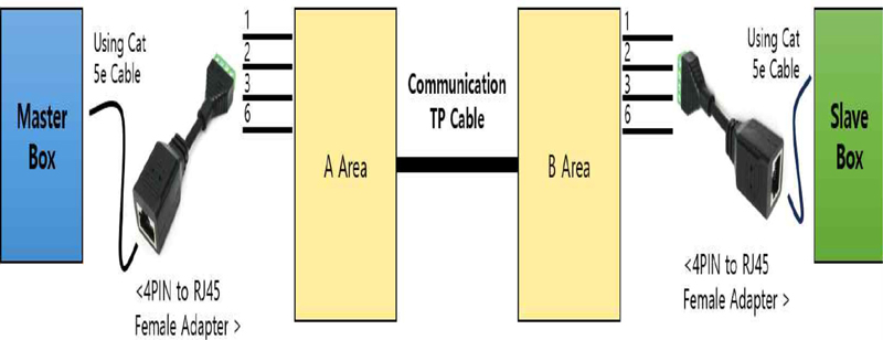
Expanding to slave box using 2 pairs of idle TP cables between A area and B area near the master box
Fig. 7 shows how to directly connect a wireless AP using two pairs of idle TP cables from area B near the slave box to area C using an RJ45 adapter. This method enables the further expansion of wireless networks to ship areas to which supplying power is challenging.
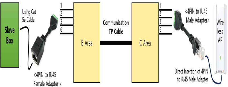
Directly connecting to the wireless access point using 2 pairs of idle TP cables between area B and C area near the slave box
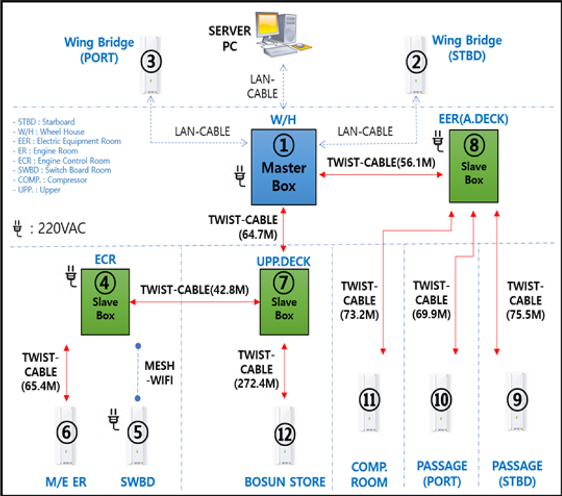
Fig. 8 presents a configuration diagram of the test ship, showing how the network is extended from the master box in the wheelhouse (W/H) to the slave boxes in the EER, Upper Deck, and ECR areas using TP cables. From these slave boxes, the wireless network was further expanded to the M/E ER, SWBD, Bosun Store, and Comp. Rooms and passage areas. For the wing bridge’s PORT and STBD areas, where TP cables were not installed, LAN cables from the master box were used to extend the wireless network.
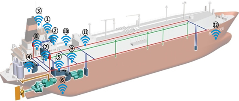
The diagram of the ship in Fig. 9 shows the locations of the areas with installed wireless APs, as depicted in the configuration diagram in Fig. 8. A total of 12 wireless APs were used in the test LNG carrier, installed in the following areas: Wheel House (①), Wing Bridge STBD (②), Wing Bridge PORT (③), Engine Control Room (④), Switch Board Room (⑤), Engine Room (⑥), Upper Deck (⑦), A Deck (⑧), Passage STBD (⑨), Passage PORT (⑩), Compressor Room (⑪), and Bosun Store (⑫).
3. RESULTS AND DISCUSSION
3.1 Testing and Performance Evaluation
The performance of the TP cables between different areas on the test ship was measured using a Fluke Networks DSX2-5000 cable analyzer set to the 10Base-T criteria. The results provide insights into the transmission speed, quality, signal attenuation, and data integrity of the cables. Among the measurement elements, the cable length represents the actual length of the TP cables used between the areas, with a maximum permissible length of 100 m. An accurate length measurement ensures the correct installation of the network and affects the signal transmission time and performance. The impedance reflects the resistance encountered by the signal as it travels through the cables. Precise impedance is critical for reducing signal reflection and ensuring data accuracy, with a standard impedance of 100 Ω and an allowable tolerance of ±15%.
The insertion loss measures the degree of signal attenuation as the signal passes through the cable, verifying whether the data can be reliably transmitted over long distances. According to the IEEE 802.3 10Base-T standard, the insertion loss should not exceed 11.5 dB over a 100-meter segment. NEXT (Near-End Crosstalk) assesses the interference between cable pairs, checking the potential for noise and errors during data transmission. The minimum NEXT value for 10Base-T was approximately 19 dB. However, the 10Base-T criterion operates at a lower speed of 10 Mbps compared with modern high-speed Ethernet standards, reducing the impact of interference on the performance.
As shown in Table 1, the performance measurements of the TP cables between areas mostly did not meet the 10 Base-T minimum NEXT requirement of 19 dB, and there were some areas with a relatively high insertion loss. While low NEXT values could affect the network performance, there were no significant issues with implementing a wireless network onboard and achieving an average network speed of approximately 70 Mbps. However, in Fig. 9, the cable connecting to the Bosun Store (⑫) exceeded 100 meters, leading to a measurement failure and a significantly lower network speed than in other areas. Despite this, a consistent network configuration was achieved on the ship and access to the server PC was possible through a wireless AP signal in the Bosun Store area.
Based on the results listed in Table 2, the average network speed across all areas of the ship when connected to the server PC was calculated to be 64.2 Mbps. This speed is sufficient for supporting stable messaging among crew members, blueprint viewing, file transfers, CCTV video streaming, and real-time monitoring and control of IP-based equipment. However, some areas recorded speeds below 30 Mbps, such as the corridors on decks C and D, and the external passage of the Upp. deck (PORT), bows, and the Bosun Store. In these areas, additional wireless APs can be installed in zones with strong surrounding AP signals, and a mesh function can be used to extend the wireless network range without additional cabling.
In addition, the ship’s Steering Gear Room, where network speed measurements could not be conducted, lacked a wireless AP, and wireless network signals from other areas were not received. Therefore, it is necessary to expand the wireless network using two pairs of idle TP cables even within separate compartments surrounded by bulkheads inside the ship.
The test ship used in this study was an LNG carrier equipped with 12 wireless APs. Network-speed measurements were conducted across all areas of the ship, both when it was docked and navigated. The results showed that in some areas, there were weak signal zones or shadow zones in which the connection was poor or measurements were not possible.
4. CONCLUSION
In this study, a wireless network was implemented throughout a test ship by integrating Power over Ethernet (PoE) network technology, which simultaneously transmits power and data over two pairs of idle communication TP cables between ship areas. Existing methods for implementing wireless networks on ships in operation, under construction, or newly built ships have shown limitations owing to their high costs, low network speeds, and reliability issues. To address these challenges, we used two pairs of preinstalled TP cables in multiple areas of the ship, along with PoE switches, extenders, wireless APs, and an AP controller for network management, thereby expanding the wireless network. Master and slave boxes were fabricated using this equipment and installed in various ship areas using two pairs of idle TP cables.
Consequently, a wireless network was established across all ship areas without the need for additional cabling for network expansion between zones, with an average measured network speed of 64.2 Mbps during navigation.
Therefore, the proposed approach is expected to provide an economical, stable, reliable, compatible, convenient, and durable wireless network for ships. Implementing a wireless network throughout a ship can connect IP-based systems, equipment, and crew member smartphones, thereby establishing an integrated operation and management system that supports efficient ship operation and maintenance.
REFERENCES
- Korea Institute of Ocean Science and Technology, Marine Fisheries Science and Technology Policy and Technology Trends, Korea Institute of Ocean Science and Technology (KIOST), Busan, 2024.
- J. U. Gong, S. G. Song, H. S. Kim, B. Y. Kim, and W. S. Sim, “Experimental Study of the Wireless Communication System by Surface Wave Communication through Confined Spaces on Vessels”, J. Navig. Port Res., Vol. 45, No. 6, pp. 366-371, 2015.
-
H. S. Kim and S. K. Kang, “A Powerline-based Legacy-line Communication System for Implementation of a Communication Network in Ship”, J. Korea Inst. Inf. Commun. Eng., Vol. 19, No. 8, pp. 1831-1838, 2015.
[https://doi.org/10.6109/jkiice.2015.19.8.1831]

- Y. S. Moon, Y. C. Bae, J. K. Park, and S. H. Roh, “The implementation of wire and wireless integration module of Zigbee and optical communication for ship area network (SAN)”, J. Korea Inst. Electron. Commun. Sci., Vol. 5, No. 5, pp. 428-434, 2010.
- IEEE 1901 Working Group, IEEE Standard for Broadband over Power Line Networks: Medium Access Control and Physical Layer Specifications, IEEE, Piscataway, 2010.
-
D. Sievenpiper, L. Zhang, R. F. J. Broas, N. G. Alexopolous, and E. Yablonovitch, “High-impedance electromagnetic surfaces with a forbidden frequency band”, IEEE Trans. Microw. Theory Tech., Vol. 47, No. 11, pp. 2059-2074, 1999.
[https://doi.org/10.1109/22.798001]

- D. M. Seo, “Networking system for integrated construction of smart ship environment”, Korean Patent No. 10-2395209, 06 Oct., 2020.
-
H. S. Kim, S. H. Park, and S. G. Kang, “Development of communication joint tools for implementing a legacy-line communication system in a train”, J. Korea Inst. Inf. Commun. Eng., Vol. 19, No. 4, pp. 877-887, 2015.
[https://doi.org/10.6109/jkiice.2015.19.4.877]

-
H. I. Jun, H. S. Kim, K. S. Jung, and K. R. Sohn, “Development of Bypass Unit for Ship Area Network Based on Legacy-line Communication”, J. Adv. Marine Eng. Technol. (JAMET), Vol. 39, No. 3, pp. 292-297, 2015.
[https://doi.org/10.5916/jkosme.2015.39.3.292]

