Development of a Structured-Light-Based 3D Vision System for Automated Installation of High-Voltage Batteries in Automotive Assembly Automation Equipment
ⓒ The Korean Sensors Society
This is an Open Access article distributed under the terms of the Creative Commons Attribution Non-Commercial License (https://creativecommons.org/licenses/by-nc/3.0/) which permits unrestricted non-commercial use, distribution, and reproduction in any medium, provided the original work is properly cited.
Abstract
With the rapid expansion of the electric vehicle (EV) market, high-voltage batteries have emerged as critical components that determine vehicle performance and safety. These batteries are mounted on the underside of the vehicle body, and positional errors may occur due to manufacturing tolerances of both the vehicle body and the battery. Such errors can lead to fastening defects and assembly failures, thereby necessitating precise measurement and compensation technologies. In this paper, a structured-light-based 3D vision system for automated installation of high-voltage batteries is proposed. The system consists of a structured-light 3D vision sensor, a point cloud generation module, a 3D region-of-interest (ROI) detection algorithm, a surface matching-based pose estimation algorithm, a hand-eye calibration algorithm, and a 6-degree-of-freedom (6-DOF) compensation algorithm. The structured-light sensor acquires 3D shape information of the battery and the vehicle underbody, generating point cloud data. The battery region is extracted through ROI detection, and surface matching is applied to estimate the 6-DOF pose. Hand-eye calibration is performed to transform the camera coordinate system into the robot coordinate system, and a compensation pose is generated to correct the installation position. The performance of the proposed system is validated using a production-like experimental environment with multiple datasets. The results demonstrate that the system satisfies the positional accuracy required for high-voltage battery installation.
Keywords:
Structured-light, 3D vision system, High-voltage battery, Surface matching, Hand-eye calibration, 6-DOF compensation1. INTRODUCTION
With the rapid growth of the electric vehicle market, high-voltage batteries based on secondary cells have become key components that determine driving range, power performance, and safety. Battery packs are typically mounted beneath the vehicle body and account for a significant portion of the total vehicle cost.
To improve assembly quality and productivity, various automated assembly technologies have been introduced in battery installation processes. However, high-voltage batteries are large structural components fastened to the vehicle body at multiple joints. Due to welding tolerances in body manufacturing and dimensional variations in battery production, positional deviations inevitably occur in practical production environments.
These deviations may cause fastening defects, reduced assembly quality, structural deformation, and degradation of battery performance. Furthermore, stress generated during the fastening process may affect vehicle reliability and durability. Therefore, precise measurement and compensation of the relative position between the battery and the vehicle body are required. Conventional battery installation systems rely on mechanical alignment devices or fixed jigs. However, such approaches are limited in handling accumulated tolerances and lack flexibility for different vehicle models. In addition, 2D vision systems are not suitable for large-scale assembly processes requiring depth information. To address these limitations, structured-light-based 3D vision and point cloud-based shape analysis techniques have been increasingly adopted in industrial assembly processes [1,3,6]. Structured light enables accurate 3D reconstruction by projecting patterns onto objects and analyzing the resulting distortions [3,6].
In this study, a structured-light-based 3D vision system for high-voltage battery installation is proposed. The system includes sensor design, point cloud processing, ROI detection, pose estimation, hand-eye calibration, and position compensation. A production-like experimental environment is constructed to evaluate the performance of the proposed system.
2. HIGH-VOLTAGE BATTERY INSTALLATION VISION SYSTEM
High-voltage batteries mounted on the underside of a vehicle body are among the most critical components of electric vehicles, and minimizing assembly errors with the vehicle body is essential. The precision of the installation position directly affects vehicle quality and safety. In particular, positional errors between the battery and the vehicle body occur on actual production lines due to welding and assembly tolerances in the body manufacturing process, as well as deviations in hole positions in the battery manufacturing process.
In this paper, a structured-light-based 3D vision system is proposed to address the positional misalignment between the high-voltage battery and the vehicle body. The proposed system encompasses overall system architecture, mechanical design, demonstration environment, signal flow, sensor configuration, and algorithm development.
Fig. 1 illustrates the conceptual diagram of the high-voltage battery installation vision system developed in this study. The structured-light-based 3D vision sensor projects patterned light onto the high-voltage battery and the vehicle underbody to acquire point cloud data, which is used to calculate the relative position between the battery and the vehicle body. The proposed vision system consists of a high-voltage battery assembly robot, a structured-light-based 3D sensor, a nut runner, and a vehicle body hanger. The assembly robot performs the fastening operation of the battery to the vehicle underbody, while the structured-light 3D vision sensor measures the six-degree-of-freedom (6-DOF) pose of the battery immediately prior to installation. The vision system's position-compensation algorithm processes the acquired point cloud data, and the resulting compensation values are transmitted to the robot controller. Based on the corrected coordinates, the robot moves to the fastening-hole positions between the battery and the vehicle body and completes the assembly process with the nut runner.
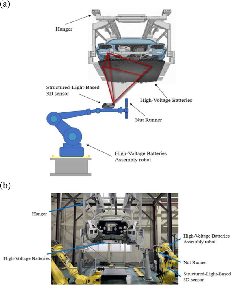
Overview of the Structured-Light-Based High-Voltage Battery Installation Vision System. (a) system concept. (b) real system.
Fig. 2 illustrates the configuration of the demonstration environment for the structured-light-based high-voltage battery installation system. The experimental setup was constructed to replicate conditions of an actual electric vehicle production line and consists of a hanger structure supporting the vehicle body, with high-voltage battery assembly robots positioned on both sides. The vehicle body is suspended at a fixed height using a hanger similar to those used on production lines, and the high-voltage battery is fixed to the hanger in a pre-assembled state, with side bolts partially fastened to the vehicle body. A structured-light-based 3D vision sensor and a nut runner are mounted on the end-effector of the battery assembly robot. The structured-light 3D vision sensor measures the geometric information of the vehicle underbody and the battery before installation, while the nut runner performs the bolt-fastening process for battery installation.
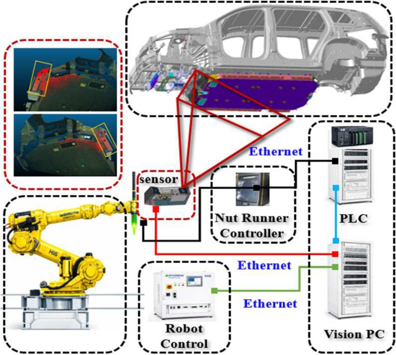
System architecture and communication configuration of the high-voltage battery installation vision system.
The structured-light 3D vision sensor acquires point cloud data of the target installation area, which is processed in real time by a vision PC. The processed results are converted into position compensation values and transmitted to the robot controller as six-degree-of-freedom (6-DOF) coordinates. Based on this information, the robot compensates for the position of the battery center holes and performs the fastening operation.
The system is designed to compensate for vehicle body positional deviations in mass production environments and to ensure that the nut runner bolts are automatically fastened to the battery mounting holes at the correct positions.
2.1 Structured-Light 3D Vision Sensor
In conventional high-voltage battery installation processes for electric vehicles, positional alignment has been achieved using reference jigs such as mechanical alignment devices or by employing 2D stereo camera systems. However, these approaches have limitations in compensating for positional errors arising from manufacturing tolerances in both the vehicle body and the high-voltage battery production processes.
Such positional errors may lead to reduced installation accuracy and fastening defects and can adversely affect the reliability of automated assembly processes.
In this study, a structured-light-based 3D vision sensor was developed to precisely measure the relative position between the high-voltage battery and the vehicle body. The structured-light 3D vision sensor consists of a high-resolution 2D camera and a projector module, and it acquires three-dimensional shape information of the target object using projected patterns [3,6].
In the developed structured-light 3D camera, the projector projects patterned light onto the target, and the high-resolution 2D camera sequentially captures the projected pattern images.
The acquired images are converted into 3D point cloud data through decoding, and the resulting data is used to compute the positions of the battery and the vehicle body [3].
In addition, the structured-light-based 3D vision sensor was developed by optimizing the optical configuration between the camera and the projector, considering the working distance, field of view (FOV), and resolution to ensure applicability in real production environments. The sensor was mechanically designed with a focus on lightweight construction and structural rigidity, taking into account the constrained installation space under the vehicle and vibration conditions in the production line.
The main specifications of the developed structured-light 3D vision sensor are summarized in Table 1, and Fig. 3 illustrates the measurement principle, mechanical design, and the fabricated sensor system.

Our developed Structured-Light-Based 3D sensor specifications.
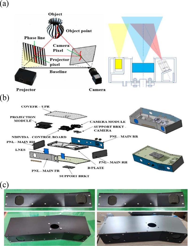
Developed Structured-Light-Based 3D Vision Sensor. (a) measurement principle. (b) 3D design. (c) real system.
2.2 3D Coordinate Generation Module
In electric vehicle high-voltage battery assembly lines, battery position measurement and compensation must be performed within the cycle time, requiring both fast processing of acquired image data and accurate 3D coordinate reconstruction in structured-light-based vision systems.
In the developed structured-light 3D vision sensor, the projector sequentially projects structured-light patterns, and the camera synchronously captures images corresponding to each pattern. The captured images are processed using a decoding procedure to establish correspondences between camera and projector image coordinates. The intrinsic and extrinsic parameters of the structured-light system are obtained through prior calibration, and the calibrated parameters are used to reconstruct 3D coordinates based on triangulation [3]. The generated point cloud data undergoes noise removal and plane correction before being used as input for the region-of-interest (ROI) detection algorithm.
To ensure the measurement accuracy required in production environments, camera calibration, projector calibration, plane fitting, and reprojection error minimization algorithms are applied [3]. These processes improve the planar accuracy and precision of the structured-light 3D vision sensor, enabling stable acquisition of point cloud data in real high-voltage battery assembly environments.
As shown in Fig. 4, a DLP4500 optical module and a DLPC350 controller chip are used to generate structured-light patterns. The module is responsible for pattern projection and projector control and interfaces with the vision PC via Ethernet. The structured-light projection module was implemented using the DLP LightCrafter 4500 Evaluation Module (EVM) (Texas Instruments, Dallas, TX, USA). The projection system is based on the DLP4500 digital micromirror device (DMD) and the DLPC350 controller, which provide programmable structured-light pattern projection for 3D reconstruction.
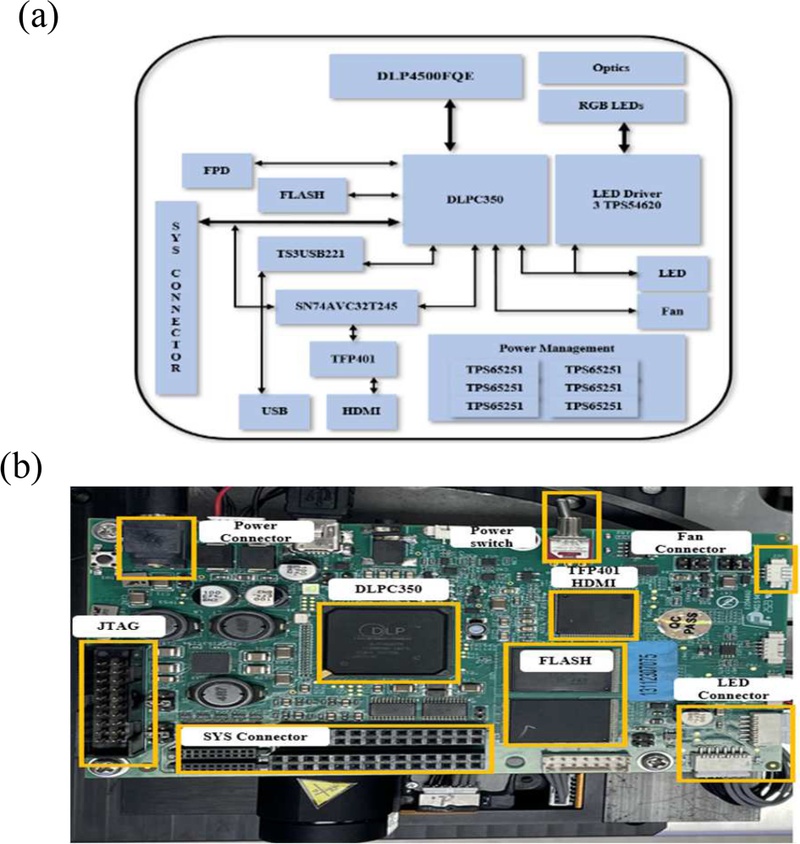
Structured-Light-Based hardware module. (a) board diagram. (b) real system.
2.3 Communication Sequence and Signal Flow
The communication and sequence signal flow of the vision system for high-voltage battery installation is based on real-time communication among the robot controller, PLC, and vision PC. When vehicle type information is received from the PLC, system initialization is performed, and the structured-light-based 3D vision sensor is activated. The robot then moves to a predefined scanning position, and the vision PC sequentially captures images of the structured-light pattern.
The acquired images are processed to generate point cloud data and to perform ROI computation. The resulting ROI-based position compensation is expressed as six-degree-of-freedom (6-DOF) parameters (Tx, Ty, Tz, Rx, Ry, Rz) and transmitted to the robot controller. Based on the received compensation data, the robot is moved to the fastening-hole positions for high-voltage battery installation, and the bolt fastening operation is performed with a nut runner.
Fig. 5 illustrates the overall signal flow among the robot, PLC, and vision PC. The calculated ROI-based position compensation values are used as input data to minimize the relative positional error between the high-voltage battery and the vehicle body. The 3D ROI detection algorithm used to compute these values is described in the following section.
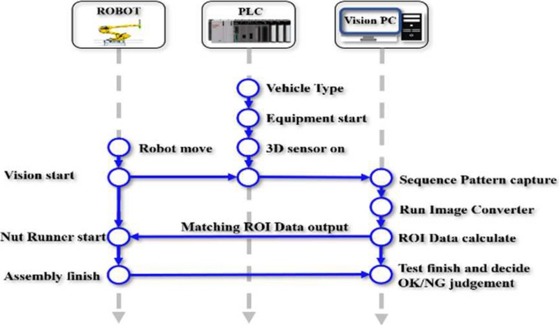
Signal flow chart of battery application inspection system.
3. 3D ROI DETECTION ALGORITHM
In electric vehicle production lines, the vehicle body and the high-voltage battery are manufactured in separate processes, resulting in positional deviations due to manufacturing tolerances. These deviations may lead to fastening errors during battery installation and adversely affect the quality and reliability of the automotive assembly system.
The proposed algorithm utilizes a structured-light-based 3D vision sensor to measure the geometric information of the battery and the vehicle underbody and to generate point cloud data. The generated point cloud data is processed through a region-of-interest (ROI) extraction procedure to isolate only the battery region. Subsequently, surface matching is applied to estimate the six-degree-of-freedom (6-DOF) pose of the battery. The estimated pose is transformed into the robot coordinate system through hand-eye calibration and is ultimately used as the robot position compensation value. The ROI extraction parameters were empirically determined through repeated experiments conducted under the actual production environment. A distance threshold was first applied to remove points outside the battery installation region. Subsequently, low-SNR points from optical reflections were removed using an SNR threshold. Morphological erosion was then performed to eliminate boundary noise, and clustering was applied to retain only the largest connected battery region. The parameter values were selected to maximize matching stability while minimizing background interference.
Fig. 6 illustrates the overall processing pipeline of the proposed 3D ROI detection algorithm. The algorithm consists of pattern capture, point cloud generation, ROI extraction, battery object generation, surface matching, pose estimation, 6-DOF compensation, and robot coordinate output.
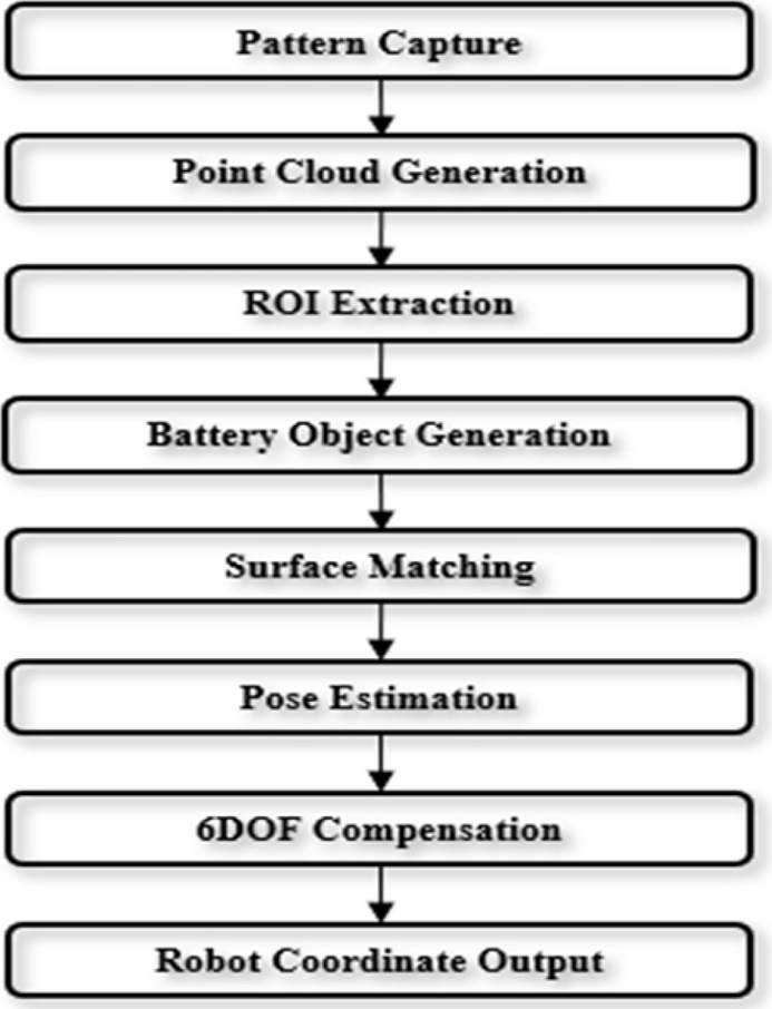
Overall flow of the proposed 3D ROI detection algorithm.
3.1 Battery Recognition Algorithm
The point cloud data acquired from the structured-light-based 3D vision sensor is used as input for estimating the position and pose of the high-voltage battery. However, point cloud data obtained in real production environments includes vehicle body structures, background regions, and measurement noise. Therefore, directly applying surface matching may degrade the accuracy of pose estimation.
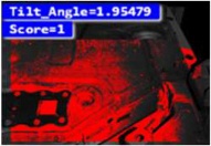
The raw data contains both the vehicle body structure and the battery region, and including background regions during surface matching may lead to incorrect pose estimates. To address this issue, distance-based filtering, SNR-based noise removal, erosion operations, and clustering techniques are applied to extract only the battery region. After ROI extraction, a final battery object is generated using only the point cloud data corresponding to the battery region. The generated battery object is then used for surface matching between the reference battery model and the measured battery object. Surface matching computes the optimal alignment by comparing the geometric features of the reference and measured models. Both models are represented in surface form, and a matching algorithm is applied to estimate their alignment [2,4,5].
From the matching results, a transformation matrix is computed that provides six degrees of freedom (6-DOF) information, including translation (Tx, Ty, Tz) and rotation (Rx, Ry, Rz) [2,5].
The surface-matching algorithm used in this study improves alignment accuracy through iterative pose optimization, and the estimated pose is subsequently used as input to the position-compensation algorithm.
3.2 Hand-Eye Calibration Algorithm
The battery pose estimated via surface matching is expressed in the camera coordinate system and cannot be applied directly to the robot controller. Therefore, hand-eye calibration is performed to establish the coordinate transformation between the vision system and the robot.
Fig. 9 illustrates the hand-eye calibration procedure applied in this study. Images are acquired at multiple positions using a calibration board, while the corresponding robot TCP (Tool Center Point) positions are simultaneously recorded. Based on these data, a transformation matrix between the camera and robot coordinate systems is computed to establish the final coordinate relationship.
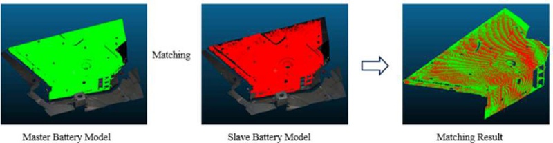
Surface matching process between the reference battery model and the measured battery object for 6-DOF pose estimation.
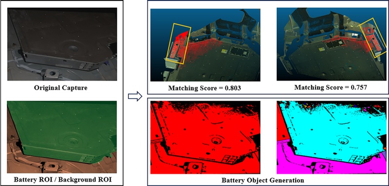
ROI extraction and battery object generation process to improve surface-matching accuracy.
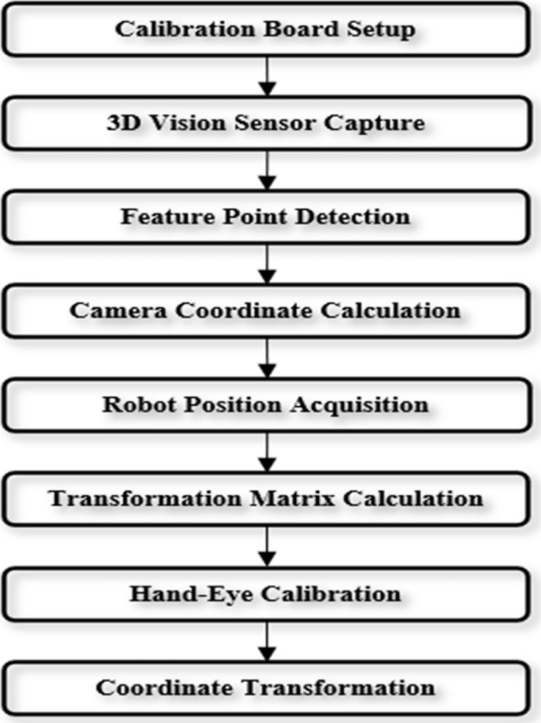
Hand-eye calibration procedure for camera-to-robot coordinate transformation.
Hand-eye calibration is generally formulated as follows:
| (1) |
Here, A represents the robot motion (pose transformation) matrix, B represents the pose transformation matrix of the calibration target observed by the camera, and X denotes the transformation matrix between the camera coordinate system and the robot TCP coordinate system [7,8]. The objective of hand-eye calibration is to determine the unknown transformation matrix X so that the camera-measured position information can be accurately transformed into the robot coordinate system.
Fig. 10 shows the calibration board images acquired for hand-eye calibration. In this study, calibration data were collected from 12 different robot poses and used to compute the coordinate transformation matrix [8,9]. By acquiring data from multiple poses, stable coordinate transformation performance was achieved across the entire robot workspace.
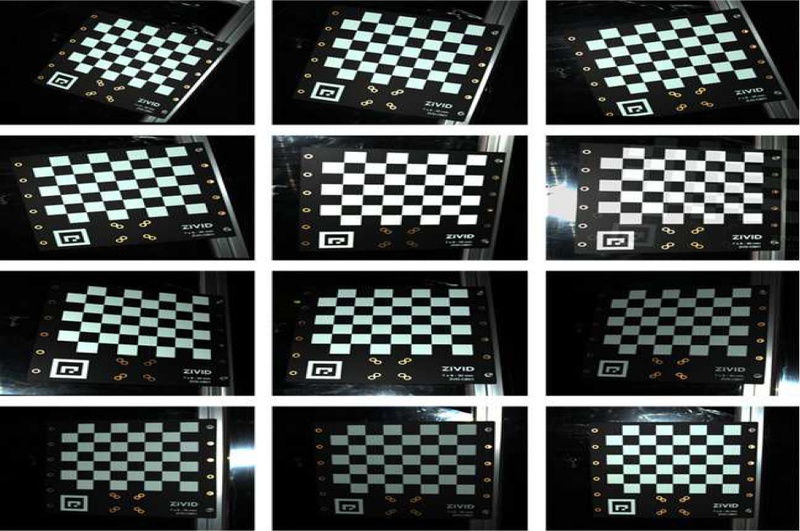
Calibration board images acquired at twelve different robot poses for hand-eye calibration.
3.3 6-DOF Compensation Algorithm
In the high-voltage battery installation process, positional errors arise from manufacturing tolerances in both the vehicle body and the battery. Therefore, real-time position compensation must be performed using the pose information estimated through surface matching.
Fig. 11 illustrates the concept of the proposed 6-DOF position compensation algorithm. The rotational errors (ΔRx, ΔRy, ΔRz) are calculated from the surface-matching results between the reference and measured battery models. The computed rotational errors are transformed into the robot's coordinate system via hand-eye calibration, yielding the final robot compensation pose.
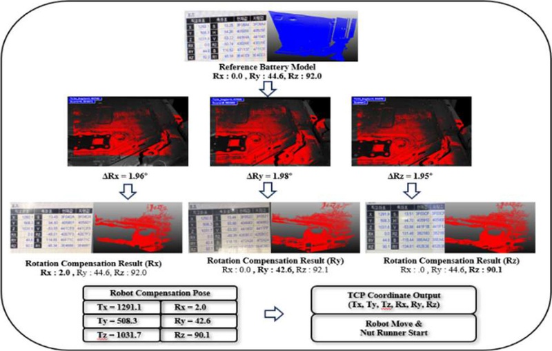
Generation of robot compensation pose based on the estimated battery pose and coordinate transformation.
The generated robot compensation pose includes translational compensation values (Tx, Ty, Tz) and rotational compensation values (Rx, Ry, Rz), expressed in the robot TCP coordinate system [7]. The final TCP coordinate output is transmitted to the robot controller, and the robot moves to the compensated position to fasten the battery using the nut runner.
By applying the proposed algorithm, the relative positional error between the vehicle body and the high-voltage battery can be effectively compensated, ensuring the installation accuracy and fastening reliability required in real production environments.
4. EXPERIMENTAL RESULTS
To validate the performance of the proposed structured-light-based high-voltage battery installation vision system, a demonstration system was constructed in an environment similar to an actual electric vehicle production line. The experimental setup consists of a vehicle body hanger, a high-voltage battery, an assembly robot, a nut runner, and a structured-light-based 3D vision sensor. A vision PC is used to perform point cloud generation and position compensation algorithms. Fig. 12 illustrates the experimental environment of the proposed system. The structured-light-based 3D vision sensor is mounted on the robot end-effector and acquires point cloud data by measuring the high-voltage battery located beneath the vehicle body. The vision PC processes the acquired data, and the final robot-compensation pose is generated via surface matching and hand-eye calibration.
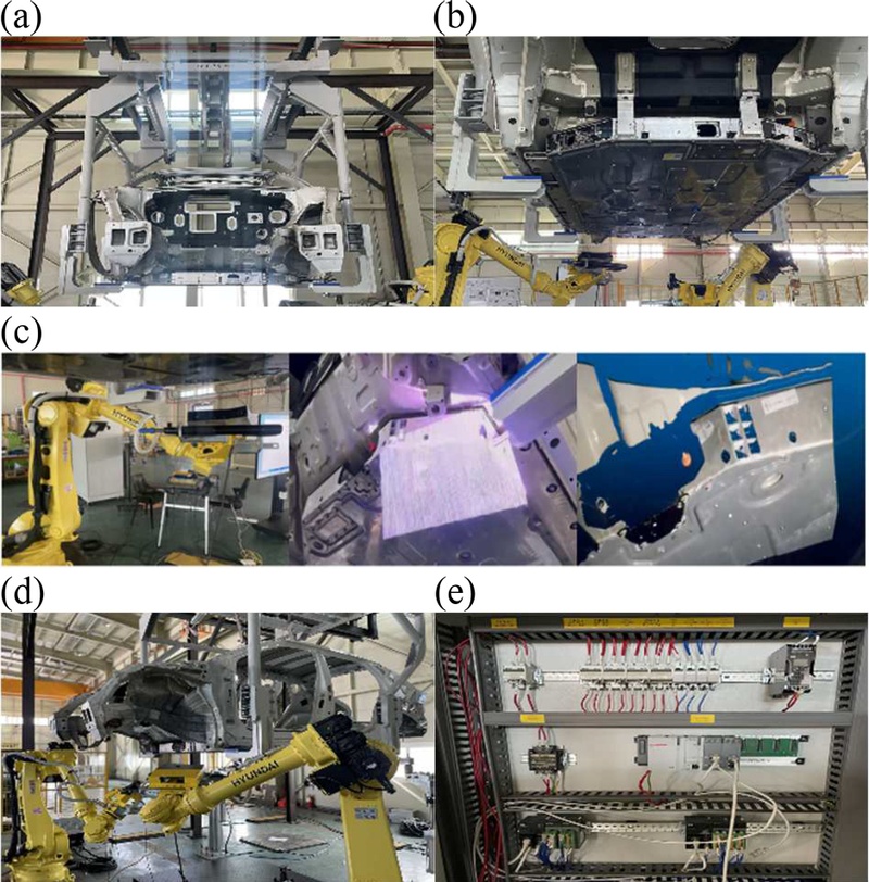
Experimental environment of the proposed high-voltage battery installation vision system. (a) Vehicle body fixture. (b) battery installation state. (c) structured-light measurement process. (d) assembly robot. (e) control PLC.
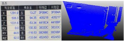
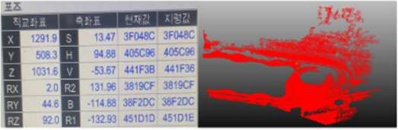
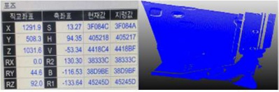
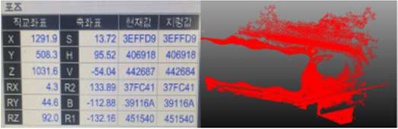
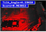
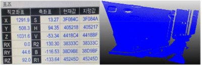
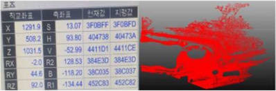
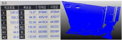
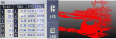
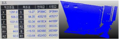
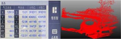
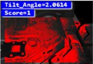
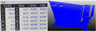
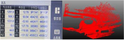
The experiments were conducted using a total of 10 evaluation datasets. Pose deviations between the reference and measured battery models were intentionally introduced, and the estimated pose from the algorithm was compared with the ground truth. The experimental data include rotational errors in the Rx, Ry, and Rz directions, and the accuracy was evaluated based on the surface matching results and the estimated 6-DOF pose.
Table 2 summarizes the experimental results for the 10 datasets. The proposed algorithm achieved an average pose estimation error of ±0.0607°, demonstrating that the required positioning accuracy for high-voltage battery installation is satisfied.
Experimental results of 6-DOF pose estimation accuracy.
The results confirm that the proposed structured-light-based vision system effectively compensates for positional deviations caused by manufacturing processes in both the vehicle body and the battery, enabling stable automated fastening in real production-line environments.
5. CONCLUSION
In this paper, a structured-light-based 3D vision system was developed to improve the precision of high-voltage battery installation in electric vehicles.
The proposed system consists of a structured-light 3D vision sensor, a point cloud generation module, a 3D ROI detection algorithm, a surface matching-based pose estimation algorithm, a hand-eye calibration algorithm, and a 6-DOF position compensation algorithm. The system measures the geometric information of the high-voltage battery and the vehicle underbody using structured-light patterns and generates point cloud data. The generated data is processed through an ROI extraction procedure to isolate the battery region, followed by surface matching to estimate the 6-DOF pose. The estimated pose is transformed into the robot coordinate system via hand-eye calibration, and a final robot-compensated pose is generated and applied to the automated installation process.
For performance validation, an experimental environment similar to an actual production line was constructed, and each dataset was generated by introducing intentional pose deviations in the Rx, Ry, and Rz directions. The experimental results show that the proposed algorithm achieves an average pose estimation error of ±0.0607°, demonstrating that the required positioning accuracy for high-voltage battery installation is satisfied. Furthermore, by applying the generated compensation coordinates to the robot TCP, stable battery installation and fastening operations were successfully achieved. Although the proposed system demonstrated high positioning accuracy in the experimental environment, the validation was conducted using a limited production-like setup and a fixed working distance. Therefore, additional verification under various vehicle platforms, battery models, and wider operating conditions will be required before practical deployment in mass-production environments.
Future work will focus on validating the applicability of the proposed system to multi-vehicle electric platforms and improving ROI extraction performance using deep learning-based object recognition techniques. In addition, real-time point cloud optimization and digital twin-based virtual validation environments will be developed to extend the system toward next-generation smart factory battery assembly automation.
Acknowledgments
This work was supported by the Technology Development Program of the Ministry of SMEs and Startups (MSS), Republic of Korea, in 2025 (Project No. S3458660, “EVx Mobility Battery Assembly Automation System for Multi-Product Flexible Manufacturing”).
REFERENCES
-
L. Jacobs, J. Dvorak, A. Cornelius, R. Zameroski, T. No, T. Schmitz, Structured light scanning artifact-based performance study, Manuf. Lett. 35 (2023) 873–882.
[https://doi.org/10.1016/j.mfglet.2023.07.014]

-
P.J. Besl, N.D. McKay, A method for registration of 3-D shapes, IEEE Trans. Pattern Anal. Mach. Intell. 14 (1992) 239–256.
[https://doi.org/10.1109/34.121791]
-
J. Geng, Structured-light 3D surface imaging: a tutorial, Adv. Opt. Photonics 3 (2011) 128–160.
[https://doi.org/10.1364/AOP.3.000128]
-
F. Pomerleau, F. Colas, R. Siegwart, A review of point cloud registration algorithms for mobile robotics, Found. Trends Robot. 4 (2015) 1–104.
[https://doi.org/10.1561/2300000035]
-
Y. He, B. Liang, J. Yang, S. Li, J. He, An iterative closest points algorithm for registration of 3D laser scanner point clouds with geometric features, Sensors 17 (2017) 1862.
[https://doi.org/10.3390/s17081862]
-
S. Zhang, High-speed 3D shape measurement with structured light methods: a review, Opt. Lasers Eng. 106 (2018) 119–131.
[https://doi.org/10.1016/j.optlaseng.2018.02.017]
-
R.Y. Tsai, R.K. Lenz, A new technique for fully autonomous and efficient 3D robotics hand/eye calibration, IEEE Trans. Robot. Autom. 5 (1989) 345–358.
[https://doi.org/10.1109/70.34770]
-
I. Enebuse, B.K.S.M. Kader Ibrahim, M. Foo, R.S. Matharu, H. Ahmed, Accuracy evaluation of hand-eye calibration techniques for vision-guided robots, PLoS ONE 17 (2022) e0273261.
[https://doi.org/10.1371/journal.pone.0273261]
-
R. Horaud, F. Dornaika, Hand-eye calibration, Int. J. Robot. Res. 14 (1995) 195–210.
[https://doi.org/10.1177/027836499501400301]