
Design and Experimental Evaluation of a TEG-Powered Batteryless BLE Node Platform using Voltage-Gated Operation

ⓒ The Korean Sensors Society
This is an Open Access article distributed under the terms of the Creative Commons Attribution Non-Commercial License (https://creativecommons.org/licenses/by-nc/3.0/) which permits unrestricted non-commercial use, distribution, and reproduction in any medium, provided the original work is properly cited.
Abstract
This paper presents a thermoelectric-generator (TEG)-powered batteryless Bluetooth Low Energy (BLE) node platform for industrial monitoring applications where battery replacement is costly or impractical. The platform converts thermal energy using two series-connected SP1848-27145 TEG modules, stores the harvested electrical energy in a 0.22 F supercapacitor through a BQ25570 energy-harvesting PMIC, and activates the BLE microcontroller only when sufficient stored energy is available. A voltage-gated architecture enables operation at approximately 5.05 V and shuts the system down at approximately 4.45 V to mitigate the risk of brownout during wireless communication. Experiments under 60, 70, and 80°C hot-plate settings evaluate TEG output, supercapacitor charging time, runtime, packet reception rate (PRR), and BLE communication energy. To keep the manuscript concise, nRF Power Profiler Kit II (PPK2) measurements are summarized as peak current, average current, and energy per communication event. Results show that beacon advertising consumes lower energy (5.21 mJ/event, 1.59 mA average current) and provides longer runtime, whereas connection-based communication achieves 100% PRR at a higher energy cost (6.63 mJ/event, 2.01 mA average current). These findings provide design guidelines for selecting BLE communication modes according to the available harvested energy in batteryless BLE node platforms.
Keywords:
Batteryless BLE node, Bluetooth low energy, Energy harvesting, Supercapacitor, Thermoelectric generator, Voltage gating1. INTRODUCTION
Industrial sensor networks are increasingly used to monitor motors, compressors, pipelines, rotating machines, and other physical assets in smart factories. These networks support predictive maintenance and safety management by collecting condition data near equipment. However, when hundreds or thousands of sensor nodes are deployed, battery replacement becomes a major maintenance burden, especially in high-temperature, enclosed, or hard-to-access areas.
Energy harvesting is an attractive alternative because it converts ambient energy sources, such as heat, vibration, and electromagnetic energy into electrical power [1-4]. Among these sources, thermal energy is widely available in industrial facilities, and a thermoelectric generator can directly convert a temperature gradient into electrical energy through the Seebeck effect [1]. Nevertheless, harvested power varies with the thermal environment and is generally insufficient for continuous wireless operation. Therefore, batteryless systems accumulate energy in a capacitor or supercapacitor and operate intermittently only after sufficient energy has been stored [3,4].
Wireless communication is one of the most energy-demanding tasks in a batteryless node. BLE transmission and connection maintenance can cause instantaneous current peaks that may drop the supply voltage below the minimum operating voltage. If the node starts communication without sufficient stored energy, a brownout, reset, or packet failure can occur. The communication strategy must be selected in conjunction with the energy storage state rather than independently of it [9,10].
This paper presents a voltage-gated TEG-based batteryless BLE node platform. This study presents the energy harvesting architecture, voltage-gated operation, and experimentally observed trade-off between BLE beacon and connection modes.
The main contributions of this study are as follows. First, a TEG-based batteryless BLE node using a BQ25570 PMIC and a supercapacitor is implemented. Second, a voltage-gated operation window is applied to mitigate the risk of brownout during BLE operation. Third, the effects of thermal conditions on TEG output, supercapacitor charging time, runtime, and PRR are experimentally evaluated. Fourth, the energy and reliability trade-off between BLE beacon advertising and connection-based communication is summarized for practical BLE-node design.
2. RELATED WORK
Energy-harvesting sensor nodes have been studied using solar, thermoelectric, piezoelectric, and electromagnetic energy sources [2-5]. These systems differ from battery-powered nodes because their input power is time-varying and strongly dependent on the surrounding environment. As a result, the node must be designed using an energy-neutral or intermittent operating model rather than a continuous-power model.
Thermoelectric energy harvesting is suitable for industrial environments because heat sources are often continuously available from motors, pipes, engines, and process equipment [1]. Hybrid harvesting methods have also been proposed to increase energy availability under combined thermal and mechanical excitation [6]. Batteryless wireless systems generally use voltage thresholds to determine when computation and communication can safely begin. Intermittent computing studies have focused on checkpointing, nonvolatile memory, and execution consistency [7,8]. However, a practical BLE node platform must also consider the energy storage device, power management circuit, and radio communication mode.
BLE advertising, connection-based BLE, LoRaWAN, and wake-up radios have each been considered for low-power wireless systems [9,10,15], and LoRaWAN- and wake-up-radio-based low-power communication methods have been examined more specifically in energy-harvesting and battery-free contexts [17,18]. In many previous studies, the energy harvesting circuit and the wireless communication protocol have been analyzed separately. In contrast, this study evaluates the operating chain from heat input to TEG output, supercapacitor charging, voltage-based activation, BLE runtime, packet reception, and communication energy. This integrated viewpoint is important because a communication mode that is reliable under stable supply conditions may not be suitable when the energy source is intermittent.
Recent studies published since 2022 have specifically examined the pairing of thermoelectric harvesting with low-power wireless links. Liu et al. [16] analyzed the end-to-end power balance of a BLE sensor node powered by two thermoelectric generators in a substation-monitoring application, reporting per-phase energy consumption for advertising and connection events measured with a dedicated power analyzer. Compared with that work, the present study additionally applies a hardware voltage-gated activation window rather than relying on a rechargeable battery buffer, and directly compares beacon and connection modes under the same voltage-gated energy budget rather than analyzing a single fixed communication mode. Riva and Zaim [17] reviewed power consumption models for battery-free LoRaWAN nodes and proposed transmission-side optimizations, which are complementary to the present BLE-based approach; the two studies differ mainly in the wireless protocol (LoRaWAN versus BLE) and in the target range and duty-cycle regime (long-range, infrequent uplinks versus short-range, higher-repetition beacon/connection traffic). Relative to general wake-up-radio surveys such as Piyare et al. [18], the proposed system uses a PMIC-level voltage comparator rather than a dedicated wake-up receiver circuit to gate MCU activation, trading the lower idle power of a true wake-up radio for a simpler, single-IC implementation suited to a TEG-supercapacitor front end. These comparisons indicate that the main contribution of the present work relative to studies published since 2022 is the joint, quantitative evaluation of TEG-based charging, voltage-gated activation, and the BLE communication-mode trade-off within one experimental chain, rather than a comprehensive point-by-point benchmark against every technical parameter of prior systems.
3. SYSTEM ARCHITECTURE AND ENERGY MODEL
3.1 Hardware Architecture
The proposed batteryless BLE node platform consists of two SP1848-27145 TEG modules connected in series, a BQ25570 energy-harvesting PMIC, a 0.22 F supercapacitor, a 3.3 V regulator, and an nRF-series BLE microcontroller. The series connection of the TEG modules increases the input voltage available to the PMIC. The BQ25570 performs energy harvesting and maximum power point tracking (MPPT), while the supercapacitor acts as an energy buffer for intermittent operation [11,12]. In the implemented power management circuit, the supercapacitor is connected to the VBAT/BAT_CON node as the main energy storage element, whereas the capacitor on the VOUT/VSYS side functions only as a local decoupling capacitor for the downstream 3.3 V supply line rather than as an additional storage element.
Fig. 1 shows the energy flow of the proposed system. Thermal energy is converted into electrical energy by the TEG modules. The harvested power is transferred to the PMIC and accumulated in the supercapacitor. The regulator and BLE microcontroller are enabled only after the supercapacitor reaches the activation threshold. This structure prevents the microcontroller from attempting wireless communication when the stored energy is insufficient.
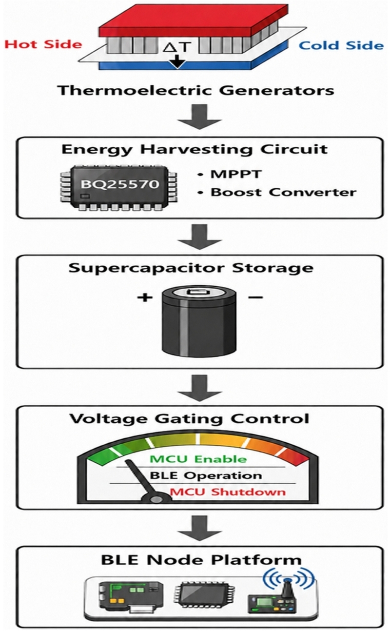
Architecture of the TEG-powered batteryless BLE node platform.
3.2 Voltage-Gated Operation and Energy Window
To relate the thermal input to the stored energy, the temperature difference across the TEG is defined as follows.
| (1) |
The TEG output voltage and generated power can then be expressed as follows.
| (2) |
| (3) |
where Thot and Tcold are the hot-side and cold-side temperatures of the TEG, respectively, S is the Seebeck coefficient, and VTEG and ITEG are the TEG output voltage and current, respectively.
The system is controlled by the supercapacitor voltage. During the charging state, the MCU and BLE circuit remain disabled. When the supercapacitor voltage reaches approximately V_ON = 5.05 V, the regulator is enabled, and the BLE node begins operation. As communication consumes energy, the supercapacitor voltage decreases. When the voltage falls below approximately V_OFF = 4.45 V, the system shuts down and returns to the charging state.
The energy stored in the supercapacitor and the dischargeable energy available during one voltage-gated operating window are calculated as follows.
| (4) |
| (5) |
where C is the supercapacitor capacitance, VSC is the supercapacitor voltage, and VON and VOFF are the MCU activation and shutdown thresholds, respectively. With C = 0.22 F, VON = 5.05 V, and VOFF = 4.45 V, Ewindow is approximately 0.627 J.
The V_ON and V_OFF thresholds were realized using the battery-good comparator (VBAT_OK) built into the BQ25570 PMIC rather than through MCU-side voltage polling. The voltage-gated control circuit was implemented by modifying the resistor-divider network of a commercial BQ25570-based energy-harvesting module (CJMCU-2557). Therefore, the circuit topology follows the PMIC's reference configuration, while the resistor values connected to the VBAT_OV, OK_HYST, OK_PROG, and VOUT_SET nodes were adjusted to obtain the target voltage thresholds used in this study. The resistor ladder is driven from the VRDIV pin: R2 (1.1 M ohm) and R3 (560 k ohm) set the VBAT_OV limit; R4 (820 k ohm), R5 (4.99 M ohm), and R6 (1.5 M ohm) form a three-resistor divider that provides both the OK_HYST and OK_PROG taps required by the upper and lower thresholds of the VBAT_OK comparator; and R7 (1 M ohm) and R8 (560 k ohm) set VOUT_SET. In the implemented circuit, VBAT_OK asserts near V_ON = 5.05 V and deasserts near V_OFF = 4.45 V, consistent with the thresholds reported in Table 1. The VBAT_OK output then gates the downstream 3.3 V BLE supply stage so that the BLE microcontroller remains disabled until the comparator indicates sufficient stored energy. Because this gating occurs in hardware ahead of the regulator, it does not depend on correct MCU firmware execution, which is the key difference from a software-only voltage check.

Hardware configuration and voltage thresholds
This hardware-based approach differs from software-only brownout mitigation. Software monitoring can react only after the MCU has already started, whereas the voltage-gated architecture withholds startup until an energy margin is available. This approach is simple and, in principle, effective for a batteryless node whose energy storage voltage is the most direct indicator of available operating energy. However, a dedicated brownout event, such as a forced supply sag below the regulator dropout voltage during an active communication burst, was not separately instrumented in this study. Therefore, the present results demonstrate stable runtime and 100% PRR in connection mode rather than direct waveform-level proof that brownout was avoided. Accordingly, the effect of the voltage-gated window is described here as brownout risk mitigation, and a representative gate-transition or supply-rail waveform is left as a target for future hardware-in-the-loop measurement.
The BLE communication energy and packet reception rate used in the evaluation are defined as follows.
| (6) |
| (7) |
where V is the supply voltage, I(t) is the measured current waveform, and Nrx and Ntx denote the number of received and transmitted packets, respectively.
4. EXPERIMENTAL METHOD
4.1 Energy Harvesting Test Setup
The energy-harvesting experiment was performed using a temperature-controlled hot plate as the heat source. The hot side of the TEG was placed on the hot plate, while a heat sink was attached to the cold side to provide natural-convection cooling. The hot-plate settings were 60, 70, and 80°C. The experiment measured the hot-side temperature, cold-side temperature, load voltage, supercapacitor voltage, charging time, BLE runtime, PRR, and communication power consumption.
The output voltage of the TEG was characterized using a 9.1 ohm load resistor. This load value was chosen as a fixed and repeatable reference load for comparing the TEG output across the three hot-plate settings. It is not the impedance-matched maximum-power-point load of the TEG pair, so the resulting V_load and power values in Table 3 characterize relative output trends with temperature rather than the true maximum available power. The supercapacitor charging experiment was performed with the TEG connected directly to the BQ25570 PMIC without the load resistor. PMIC MPPT sampling ratio (VOC_SAMP) was left at its default open-circuit-voltage fraction rather than being re-tuned specifically for the SP1848-27145 TEG pair [11]. Therefore, the charging time reflects not only the TEG output capability but also MPPT operation, PMIC conversion efficiency, thermal transient effects, and heat-transfer losses between the heat source, the TEG, and the heat sink. The hot-side and cold-side TEG surface temperatures (T_hot, T_cold) reported in Table 3 were measured after the hot plate reached its steady-state setting, and the corresponding temperature differences ΔT = T_hot − T_cold were 9.02°C at the 60°C setting, 14.22°C at the 70°C setting, and 18.85°C at the 80°C setting. The experiments were conducted in an indoor laboratory environment at an ambient temperature of approximately 20°C and a relative humidity of 30%, with natural-convection cooling on the TEG cold side as noted above. The values reported in Table 3 (TEG output and supercapacitor charging characteristics) and the corresponding Fig. 3 are single-trial measurements at each hot-plate condition, since this experiment was intended mainly to confirm the TEG output and charging trends across thermal conditions rather than to establish tight statistical bounds; accordingly, the conclusions drawn from Table 3 and Fig. 3 in Section 5.1 are limited to the specific thermal conditions tested. In contrast, the runtime and PRR results in Table 4 and Fig. 4 in Section 5.2 are each based on two repeated trials per condition, and the reported values are the mean of the two trials; the trial-to-trial spread was small for connection-mode runtime, with a range of 11-19 s, but noticeably larger for beacon-mode PRR with a range of about 0.5-3.3 percentage points across the two trials at a given temperature. This variation should be considered when interpreting the beacon PRR trend in Section 5.2. The PPK2 power results in Table 5 (Section 5.3) were obtained from a single steady-state current-waveform capture per communication mode, taken once each mode had settled into its regular 1,000 ms event pattern; because this steady-state BLE current draw is governed by the firmware and radio behavior rather than the TEG thermal condition, the same Table 5 values are used across all three hot-plate settings rather than being repeated for each temperature.
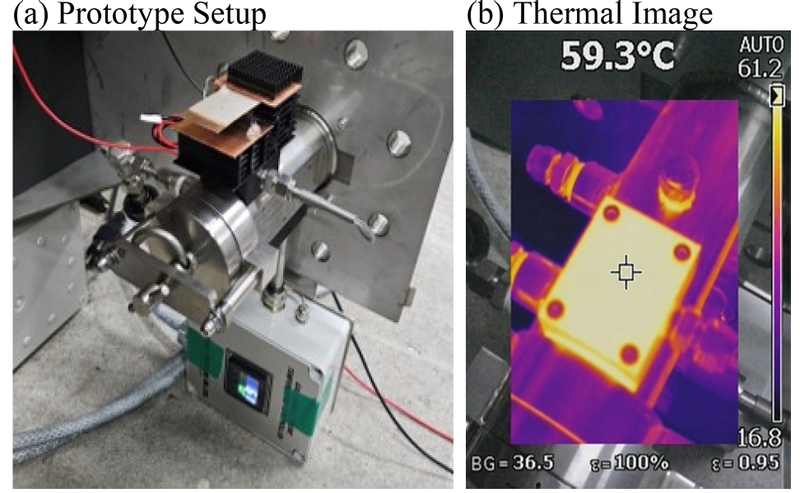
Experimental setup for TEG energy harvesting. (a) prototype setup. (b) thermal image.
BLE communication modes used in the experiment.
TEG output and supercapacitor charging characteristics.
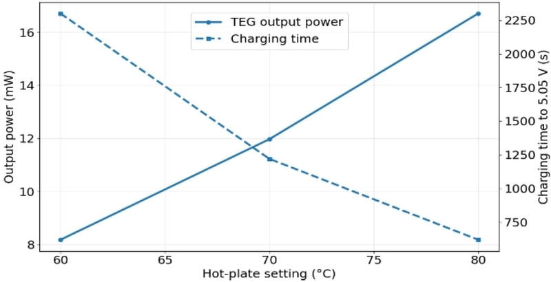
TEG output power and supercapacitor charging time under different thermal conditions.
Runtime and packet reception rate of BLE communication modes.
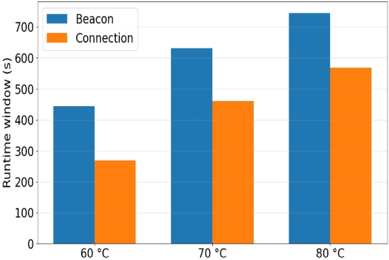
Runtime comparison between BLE beacon and connection modes.
PPK2-based power consumption summary of BLE communication modes.
4.2 BLE Communication Modes and Measurement Conditions
Two BLE communication modes were evaluated. In beacon mode, the node periodically broadcasts advertising packets without establishing a connection. This mode has low overhead and is suitable for simple status reporting or event notification. In connection mode, the node exchanges data after establishing a BLE connection with a central device. This mode provides reliable link-layer communication but requires additional energy for connection establishment, synchronization, and maintenance [13].
For a fair comparison, both modes used a 1,000 ms interval and a 6-byte payload consisting of a 2-byte supercapacitor voltage reading (mV), a 1-byte state-of-charge percentage, a 1-byte operating-mode/status byte, a 1-byte flag byte encoding the voltage-gate lockout state, and a 1-byte sequence counter. In beacon mode, one advertising event consists of transmissions on the three advertising channels. In connection mode, one data exchange occurs per connection interval as a GATT notification, and retransmission can be handled by the BLE link layer. Table 2 summarizes the two communication modes and the design implication of each mode in a batteryless environment. No external physical sensor such as a temperature or vibration sensor was attached to this prototype; instead, the payload carries the node’s own live telemetry, namely the supercapacitor voltage, state-of-charge percentage, operating mode, voltage-gate lockout status, and a sequence number, which are sampled internally by the MCU at each transmission rather than data from an externally attached sensor. The 6-byte payload itself does not include an application-layer checksum. Payload integrity relies on the BLE link layer’s own 24-bit CRC, so a corrupted packet is discarded by the BLE controller before it reaches the application. The sequence byte serves a different purpose, namely detecting lost packets (through gaps in consecutive sequence numbers) for the PRR calculation in Section 5.2, rather than detecting bit-level corruption. Accordingly, this paper refers to the implemented prototype as a “BLE node platform” rather than a “sensor node” throughout to accurately reflect the tested scope. Integration with an external physical sensor and characterization of the associated additional energy cost are identified as future work in Section 6.
The PRR results in Section 5.2 were obtained under a single fixed link configuration rather than a swept parameter study. The receiving/scanning device was a laptop computer (LG 17Z90R-GP76ML) running the scanning application, and the transmitter was an nRF52840 Nano V2 module using its default TX power setting of 0 dBm on the BLE 1M PHY. The transmitter-receiver distance was fixed at approximately 80 cm under line-of-sight conditions throughout all trials. The numbers of transmitted and received packets (N_tx, N_rx) were logged directly during the runtime test (Table 4) rather than estimated. Averaged over the two repeated trials at each temperature, beacon mode gave N_tx/N_rx values of approximately 435/72.5 at 60°C, 621/88 at 70°C, and 735.5/127.5 at 80°C. Connection mode, which achieved 100% PRR, gave N_tx = N_rx values of approximately 269, 461, and 569 at the same three temperatures, consistent with the runtimes in Table 4. Because PRR in beacon mode depends on the relationship between the advertising interval and the scanner's duty-cycled scan window, the PRR values reported in Table 4 should be interpreted as applying specifically to this scan configuration rather than as a general property of BLE beacon advertising; a longer scan window or continuous scanning would be expected to increase the beacon PRR. Additional baseline measurements under continuous scanning are a natural extension of this work but were not required to support the present conclusions.
5. RESULTS AND DISCUSSIONS
5.1 TEG Output and Supercapacitor Charging
The TEG output increased as the hot-plate setting increased. The measured average load voltage across the 9.1 ohm resistor was 0.273 V at 60°C, 0.330 V at 70°C, and 0.390 V at 80°C, corresponding to output powers of 8.18, 11.97, and 16.71 mW, respectively. These results confirm that the TEG can generate power at a level suitable for intermittent operation when combined with energy buffering.
The charging time required to reach the 5.05 V activation threshold decreased with increasing temperature. The average charging time was approximately 2,301 s corresponding to about 38.4 min at 60°C, 1,220 s (about 20.3 min) at 70°C, and 618.5 s (about 10.3 min) at 80°C. In practical terms, the 80°C condition supports intermittent status or alarm reporting roughly every 10 min, whereas the 60°C condition is better suited to low-frequency monitoring on a roughly 40 min cycle. These results show that more favorable thermal conditions shorten the system activation cycle and allow the node to communicate more frequently. However, the charging time should not be interpreted using only the ideal load-resistor output, because the actual charging process is affected by the PMIC operating point and the thermal stabilization process.
The measured temperature difference also contains uncertainty because the hot-side and cold-side values are surface temperatures. The effective internal temperature gradient across the TEG can be lower than the measured surface temperature difference owing to thermal contact resistance, non-uniform pressure, thermal interface conditions, and natural-convection limitations on the cold side. Therefore, the measured output does not increase perfectly linearly with the measured surface temperature difference.
5.2 Runtime and Packet Reception Rate
The runtime window was defined as the time from MCU activation at 5.05 V to shutdown at 4.45 V. Beacon mode provided a longer runtime than connection mode under all temperature conditions. At 60°C, the beacon and connection modes operated for 445 s and 269 s, respectively. At 80°C, the runtimes increased to 745 s and 569 s, respectively, because the TEG continued to replenish energy during BLE operation.
Communication reliability showed the opposite trend. Beacon mode achieved PRRs of 14.2-17.3%, mainly because the scanner operated with an intermittent scan window and some advertising events occurred during scan-inactive periods. Connection mode achieved 100% PRR under the test conditions because packet delivery was supported by link-layer connection management and retransmission. Thus, beacon mode is more energy-efficient, whereas connection mode is reliability-oriented.
The measured runtimes were longer than the simple discharge-only estimates calculated from Eq. (5) expressed as t = E_window/(V × I_avg). This is because the TEG continues to charge the supercapacitor while the BLE node is operating. Therefore, the effective discharge power is determined by the difference between the BLE consumption power and the harvested power. This dynamic charge-discharge balance becomes especially important at higher thermal input levels.
5.3 PPK2 Current Measurement Summary
The original waveform-level PPK2 measurements included BLE initialization, advertising repetition, connection establishment, and steady-state operation. In this version, these waveform-level descriptions are condensed into Table 5 because the principal design conclusion can be derived from the average current and event energy. This reduction avoids occupying excessive manuscript space while retaining the quantitative power evidence needed for design [14]. The PPK2 was operated in ampere-meter mode using its default sampling configuration. For each mode, a steady-state current waveform was captured over a 10.0 s window once the node had settled into its regular 1,000 ms advertising or connection-event pattern. The average current over that window was used in Eq. (6), together with the 1,000 ms communication interval to obtain the energy per event. Consequently, the ‐Energy/event‐ values in Table 5 represent the average energy consumed per periodic 1 s communication cycle during steady-state operation, including both the radio-transmission burst and the baseline sleep current between events, rather than the energy of the radio-transmission burst alone.
The peak currents of the two modes were similar, at 12.61 mA for beacon mode and 12.7 mA for connection mode. This confirms that both modes draw comparable instantaneous current during the radio-transmission burst, consistent with the BLE TX operating current range in the nRF52840 datasheet [12]. The steady-state average current was lower in beacon mode at 1.59 mA than in connection mode at 2.01 mA. The higher average current in connection mode reflects the additional link-layer synchronization and keep-alive overhead needed to maintain an established BLE connection, beyond the single periodic advertising burst used in beacon mode. For a 3.3 V supply and a 1-s communication interval, the event energy calculated using Eq. (6) is approximately 5.21 mJ for beacon mode and 6.63 mJ for connection mode. Therefore, connection mode consumes about 27% more energy per communication event than beacon mode. This higher per-event energy is consistent with the shorter runtime of connection mode observed in Section 5.2 under the same voltage-gated energy window. However, the measured runtimes for both modes were substantially longer than a simple E_window/(V x I_avg) estimate would predict, because the TEG continues to charge the supercapacitor during BLE operation and thereby reduces the net discharge rate. This dynamic charge-discharge effect is discussed further below.
The PPK2 results indicate that peak current alone is not sufficient for mode selection. Both modes require similar instantaneous current, so the supercapacitor and regulator must tolerate the peak. However, average current and event energy determine how long the node can remain active and how many packets can be transmitted in one energy window.
5.4 Design Implications for Batteryless BLE Nodes
The experimental results show that the thermal environment, energy storage window, communication mode, and packet reliability are tightly coupled. A fixed communication strategy can be inefficient because the available energy varies with the heat source. Under low-temperature conditions or after a long idle period, beacon mode can maximize the number of possible transmissions within the available energy window. Under high-temperature conditions, connection mode can be used when the application requires reliable packet delivery. These findings are consistent with previous BLE studies reporting an energy-latency-reliability trade-off between advertising /scanning and connected operation [9,10,16-18].
An adaptive strategy can be implemented by monitoring the supercapacitor voltage and the recent charging rate. If the voltage rises quickly and remains near the activation threshold, the node can use connection mode for reliable data transfer. If the voltage decreases quickly or the harvested power is low, the node can use beacon mode or postpone transmission until the next charging cycle. Such a rule can be implemented without a complex algorithm because the supercapacitor voltage provides a direct estimate of the stored energy.
5.5 Field Deployment Considerations
For field deployment, the measured surface temperature should not be treated as the actual TEG junction temperature. Contact pressure, thermal interface material, heat-sink orientation, airflow, and surface contamination can change the effective temperature gradient and charging time. Therefore, an installation-level calibration step should record the supercapacitor charging rate after mounting and use it as a practical indicator of harvested power. The voltage thresholds should also include margins for regulator dropout, supercapacitor ESR, BLE boot energy, and the first communication event.
The communication policy should be linked to the importance of the application data. Normal periodic status packets can use beacon advertising, whereas alarms, abnormal sensor values, or maintenance-request messages should switch to connection mode only when the charging rate indicates sufficient energy margin. This rule keeps the node simple, avoids unnecessary connection overhead, and preserves packet reliability for high-priority events. It also makes the proposed architecture suitable for short-payload industrial monitoring, such as equipment-state flags, temperature alarms, and low-rate vibration summaries.
6. CONCLUSIONS
This paper presented a TEG-powered batteryless BLE node platform with voltage-gated operation. The proposed system stores harvested electrical energy in a supercapacitor through a BQ25570 PMIC and activates the BLE microcontroller only within a safe operating window. Experiments under 60, 70, and 80°C hot-plate settings confirmed that higher thermal input increased TEG output power from 8.18 to 16.71 mW and decreased the supercapacitor charging time from approximately 2,301 to 618.5 s.
The results also showed a clear communication trade-off. Beacon mode consumes less energy and provides longer runtime, whereas connection mode provides higher packet reliability at a greater energy cost. The PPK2 current measurements were summarized as peak current, average current, and event energy rather than presented as multiple waveform figures. This reduction keeps the manuscript concise while preserving the values required for batteryless-node design.
Future work will include real-time adaptive BLE mode selection based on supercapacitor voltage, harvested-power estimation, and application-level reliability requirements. Integration with a physical sensor such as temperature, vibration, or equipment-state sensing and characterization of its additional energy cost within the voltage-gated window are also planned. Because the TEG output and charging-time values reported here represent relative trends under a fixed reference load rather than benchmarked against a specific industrial equipment specification, comparison of the harvested-power and charging-time results with the rated requirements of target industrial equipment is also planned as future work. Long-term testing on actual industrial equipment will also be required to evaluate heat-source fluctuations, airflow, wireless interference, and installation-condition effects on the batteryless operating cycle.
Acknowledgments
This research received no external funding.
REFERENCES
-
G.J. Snyder, E.S. Toberer, Complex thermoelectric materials, Nat. Mater. 7 (2008) 105–114.
[https://doi.org/10.1038/nmat2090]

-
S. Roundy, P.K. Wright, J. Rabaey, A study of low level vibrations as a power source for wireless sensor nodes, Comput. Commun. 26 (2003) 1131–1144.
[https://doi.org/10.1016/S0140-3664(02)00248-7]
-
D. Brunelli, C. Moser, L. Thiele, L. Benini, Design of a solar-harvesting circuit for batteryless embedded systems, IEEE Trans. Circuits Syst. I Regul. Pap. 56 (2009) 2519–2528.
[https://doi.org/10.1109/TCSI.2009.2015690]
-
A. Kansal, J. Hsu, S. Zahedi, M.B. Srivastava, Power management in energy harvesting sensor networks, ACM Trans. Embed. Comput. Syst. 6 (2007) 32.
[https://doi.org/10.1145/1274858.1274870]
-
V. Raghunathan, A. Kansal, J. Hsu, J. Friedman, M. Srivastava, Design considerations for solar energy harvesting wireless embedded systems, Proceedings of IPSN, Los Angeles, CA, USA, 2005, pp. 457–462.
[https://doi.org/10.1109/IPSN.2005.1440973]
-
S.-B. Kim, J. Shin, H.-S. Kim, D.-G. Lee, J.-C. Park, J.M. Baik, et al., A synergetic effect of piezoelectric energy harvester to enhance thermoelectric power: An effective hybrid energy harvesting method, Energy Convers. Manage. 298 (2023) 117774.
[https://doi.org/10.1016/j.enconman.2023.117774]
-
D. Balsamo, A.S. Weddell, G.V. Merrett, B.M. Al-Hashimi, D. Brunelli, L. Benini, Hibernus: Sustaining computation during intermittent supply for energy-harvesting systems, IEEE Embedded Syst. Lett. 7 (2015) 15–18.
[https://doi.org/10.1109/LES.2014.2371494]
-
A. Colin, B. Lucia, Chain: Tasks and channels for reliable intermittent programs, Proceedings of ACM OOPSLA, Amsterdam, Netherlands, 2016, pp. 514–530.
[https://doi.org/10.1145/2983990.2983995]
-
M. Siekkinen, M. Hiienkari, J.K. Nurminen, J. Nieminen, How low energy is Bluetooth Low Energy? Comparative measurements with ZigBee/802.15.4, Proceedings of IEEE WCNC Workshops, Paris, France, 2012, pp. 232–237.
[https://doi.org/10.1109/WCNCW.2012.6215496]
-
M. Dodangeh, M.S. Oude Alink, B. Nauta, Quantifying the trade-off between latency and power consumption in Bluetooth Low Energy and its mitigation by using a wake-up receiver, Proceedings of IEEE WF-IoT, Yokohama, Japan, 2022, pp. 1–8.
[https://doi.org/10.1109/WF-IoT54382.2022.10152115]
- Texas Instruments, BQ25570 Nano Power Boost Charger and Buck Converter for Energy Harvester Powered Applications. https://www.ti.com/lit/ds/symlink/bq25570.pdf, , 2015 (accessed 29 June 2026).
- Nordic Semiconductor, nRF52840 Product Specification, Version 1.7. https://docs.nordicsemi.com/bundle/ps_nrf52840, , 2021 (accessed 29 June 2026).
- Bluetooth SIG, Bluetooth Core Specification, Version 5.3. https://www.bluetooth.com/specifications/specs/core-specification-5-3/, , 2021 (accessed 29 June 2026).
- Nordic Semiconductor, nRF Power Profiler Kit II (PPK2) User Guide. https://docs.nordicsemi.com/bundle/ug_ppk2, , 2021 (accessed 29 June 2026).
-
Z.A. Eu, H.-P. Tan, W.K.G. Seah, Design and performance analysis of MAC schemes for wireless sensor networks powered by ambient energy harvesting, Ad Hoc Netw. 9 (2011) 300–323.
[https://doi.org/10.1016/j.adhoc.2010.07.014]
-
Y. Liu, J.-R. Riba, M. Moreno-Eguilaz, Energy balance of wireless sensor nodes based on Bluetooth Low Energy and thermoelectric energy harvesting, Sensors 23 (2023) 1480.
[https://doi.org/10.3390/s23031480]
-
C. Riva, A. H. Zaim, A comparative study on energy harvesting battery-free LoRaWAN sensor networks, Electrica 23 (2023) 40–47.
[https://doi.org/10.5152/electrica.2022.21101]
-
R. Piyare, A.L. Murphy, C. Kiraly, P. Tosato, D. Brunelli, Ultra low power wake-up radios: A hardware and networking survey, IEEE Commun. Surv. Tutor. 19 (2017) 2117–2157.
[https://doi.org/10.1109/COMST.2017.2728092]