
Microstructured Self-Interfacing Transparent Flexible Heater for Enhanced Thermal Coupling

ⓒ The Korean Sensors Society
This is an Open Access article distributed under the terms of the Creative Commons Attribution Non-Commercial License (https://creativecommons.org/licenses/by-nc/3.0/) which permits unrestricted non-commercial use, distribution, and reproduction in any medium, provided the original work is properly cited.
Abstract
Transparent flexible heaters require efficient thermal coupling with target surfaces to deliver generated heat uniformly. Interfacial separation creates air-filled gaps that impede heat transfer. Bonding layers introduce additional thermal boundaries and may leave residues, whereas external compression requires loading structures that constrain deformation. Here, we introduce a self-interfacing transparent flexible heater that maintains contact without a separate bonding layer or sustained external compression. The device integrates a silver nanowire heating network with mushroom-shaped micropillars bearing extruded tips, providing adhesion strengths up to ten times those of flat and tip-free pillar controls. The heater reaches approximately 120°C at 8 V, with a temperature distribution comparable to that of an Ag-paste-bonded reference. The heater detaches without the paste residues or clip-induced surface damage observed with the reference configurations. Finite-element analysis indicates that the microstructured cavities alter heat partitioning, while prescribed interfacial separation retains more heat within the heater and reduces heat transfer to the substrate. These results show that microstructured interfaces can combine mechanical attachment with heat delivery in transparent flexible heaters.
Keywords:
Flexible heaters, Silver nanowires, Interfacial contact, Heat transfer, Bioinspired adhesion1. INTRODUCTION
Flexible heaters provide conformal, lightweight, and efficient thermal control for wearable electronics, soft robotic systems, biomedical devices, and building-integrated applications [1-4]. Their mechanical compliance enables conformal heating of curved or deformable surfaces without constraining deformation. Most flexible heaters rely on Joule heating, offering rapid electrothermal responses and compatibility with scalable film-processing techniques [5]. These characteristics may also be useful for thermal control in emerging embodied systems that integrate sensors and soft actuators and operate under changing environmental conditions [6,7]. Across these applications, performance depends not only on heat generation within the heater but also on the efficiency and uniformity of heat transfer to the target surface.
Transparent flexible heaters (TFHs) provide thermal control while preserving optical transmission, making them suitable for windows, optical sensors, and photovoltaic devices [8-10]. A TFH requires a conductive layer that combines low sheet resistance, high optical transmittance, and electrical stability under deformation [11,12]. Materials investigated for this purpose include silver nanowires (AgNWs), carbon nanotubes, graphene, and MXenes [11,13-15]. Among them, AgNW networks are widely used because they form percolated conductive pathways at low areal coverage, thereby preserving transparency and flexibility. Recent studies have improved AgNW-based heaters through oxide encapsulation, core–shell nanowire architectures, and junction welding [16-20]. Previous studies have mainly focused on the electrical and optical properties of the heater film, with less attention given to its thermal contact with the target surface.
Interfacial contact is commonly improved by introducing a thermal interface material (TIM) or applying an external compressive load [21,22]. TIMs can conform to surface irregularities and displace trapped air, but they create an additional heat-transfer layer. Its thickness and thermal conductivity determine the bulk resistance, while the two newly formed material boundaries contribute further interfacial resistance. Depending on their composition and geometry, TIMs may also reduce optical transparency, complicate fabrication, or leave residues on the contacted surface. Direct compression avoids a separate layer and can increase the real contact area by deforming surface asperities [23]. Uniform pressing can establish effective contact during assembly or testing, but the contact may deteriorate after the load is removed because of elastic recovery and surface waviness. For nonadhesive interfaces, maintaining the improved contact therefore requires a continuous loading structure, which adds bulk and constrains mechanical deformation [21]. An effective TFH interface must therefore maintain a sufficiently large and distributed contact area without a separate bonding layer or sustained external loading.
Here, we develop and systematically evaluate a self-interfacing transparent flexible heater (SFH) that integrates an AgNW Joule-heating network with mushroom-shaped micropillars bearing extruded tips (Fig. 1). Building on related interfaces previously used to investigate nanowire properties in self-adhesive transparent electrodes [19] and thermal contact resistance in self-interfacing thermal devices [24], the present work examines electrothermal behavior within an integrated heater platform. The SFH maintains attachment after the placement load is removed without a separate bonding layer or sustained external compression. Across the tested substrates, the extruded-tip structure exhibits adhesion strengths up to ten times those of flat and tip-free pillar controls. The SFH reaches approximately 120°C at 8 V with heating uniformity comparable to that of an Ag-paste-bonded reference, whereas clip fixation produces localized heating and fails at 5 V. Surface profilometry detects residues after Ag paste removal and scratches after clip fixation, but no detectable residue or damage after SFH detachment. Finite-element analysis indicates that the micropillar-containing designs alter heat partitioning and that increasing the prescribed air-gap size leads to a progressive loss of thermal coupling. These results demonstrate that microstructuring the heater–substrate interface can enhance thermal coupling, providing a practical route to improve heat delivery from TFHs without an additional bonding layer or sustained external compression.
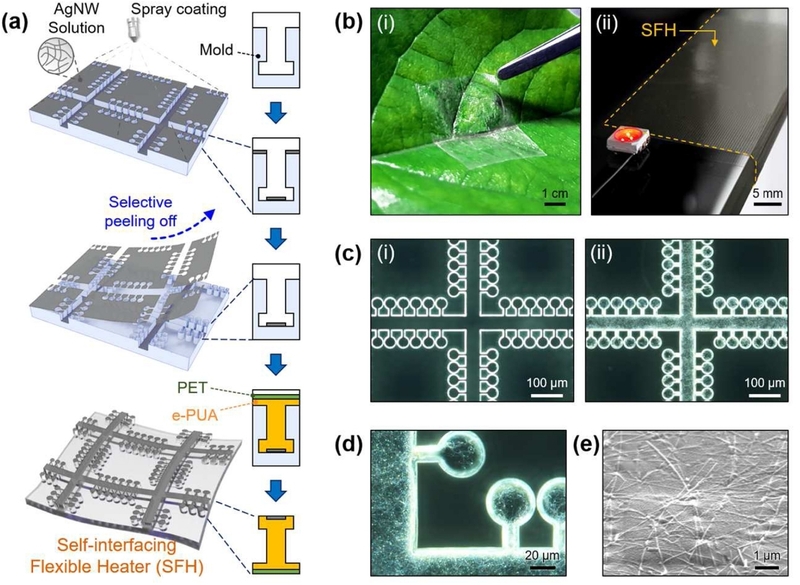
Fabrication and structural characterization of the self-interfacing transparent flexible heater. (a) Schematic of the fabrication process. (b) Photographs showing (i) conformal attachment to a leaf and (ii) an LED illuminated through the device. (c) Dark-field micrographs (i) before and (ii) after AgNW integration. (d) Enlarged view of the extruded-tip micropillars and patterned AgNW network. (e) SEM image of the AgNW network.
2. EXPERIMENTAL
2.1 Materials
An aqueous silver nanowire (AgNW) dispersion containing 0.1 wt% AgNWs and 0.05 wt% hydroxypropyl methylcellulose was obtained commercially (Flexio Corp., Republic of Korea). The AgNWs had an average diameter of 20 nm and an average length of 20 μm. Lift-off resist (LOR 30B), SU-8 photoresist (SU-8 3010), and SU-8 developer were obtained from MicroChem Corp. (USA). AZ 400 K developer was obtained from AZ Electronic Materials Corp. (USA), and Triton X-100 was obtained from Sigma-Aldrich (USA).
2.2 Fabrication of the device
Master molds for the flat, tip-free micropillar, and extruded-tip micropillar structures were fabricated on Si wafers using a previously reported bilayer photolithography process with LOR 30B and SU-8 3010 [24]. For the extruded-tip structure, a 2 μm undercut was formed beneath the SU-8 patterns by selectively developing the underlying LOR layer. The AgNW dispersion was spray-coated onto the patterned master mold. The AgNW coating dose was adjusted to 0.6, 1.2, 1.8, 2.4, or 3.0 mg cm-2. The coated mold was dried at 70°C for 1 h. AgNWs deposited outside the recessed patterns were removed using commercial adhesive tape, leaving the patterned AgNW network on the mold. The elastic polyurethane acrylate (e-PUA) precursor was prepared according to a previously reported procedure [24]. The resulting mixture was deposited onto the AgNW-patterned mold and covered with a PET film. The e-PUA was crosslinked by ultraviolet irradiation for 30 min at a wavelength of 365 nm and a dose of 300 mJ cm-2. The cured e-PUA/PET film was demolded to obtain the heater with selectively integrated AgNW pathways. The flat surface (Design I), tip-free micropillars (Design II), and extruded-tip micropillars (Design III) were fabricated under the same coating and curing conditions.
2.3 Structural, Electrical, and Optical Characterization
The AgNW network and microstructured surface were examined using a scanning electron microscope (Quanta 200 FEG, FEI, USA). Before SEM imaging, the samples were sputter-coated with a 5 nm Pt layer. Optical transmittance was measured over a wavelength range of 400–800 nm using a UV–Vis–NIR spectrophotometer (Cary 5000, Agilent, USA). The transmittance values reported in this study were measured at 550 nm. Sheet resistance was measured by the four-point-probe method using a surface resistivity meter (CMT-SR1000N, Advanced Instrument Technology, Republic of Korea).
2.4 Adhesion Measurements
Adhesion strength was measured using a custom-built tester consisting of a fixed lower substrate stage and a vertically movable upper jig connected to a load cell (KTOYO, Republic of Korea). Heater samples with an apparent contact area of 1 × 1 cm2 were mounted on the upper jig with the microstructured surfaces facing downward. Each sample was brought into contact with the test substrate under a preload of 400 kPa for 10 s. This pressure served only as the initial placement load; no compressive load was maintained during the subsequent retraction and pull-off measurement. The upper jig was then retracted at 1 mm s-1 until detachment occurred. Adhesion strength was calculated by dividing the maximum pull-off force by the apparent contact area. Five independent samples were tested for each condition, and the results were reported as the mean ± standard deviation. Before testing, the glass, Cu, Si, and PET substrates were cleaned with ethanol and dried using an air gun. No additional surface treatment was applied, and surface roughness was not independently measured.
2.5 Electrothermal Characterization
Electrothermal measurements were performed using heaters with a sheet resistance of approximately 15 Ω sq-1. At 1 V, the corresponding nominal current and input power were approximately 0.067 A and 0.067 W, respectively, as calculated using P=V2/R. All configurations were subsequently evaluated using the same voltage-control protocol without active regulation of the current or input power.
Surface-temperature distributions were recorded using an infrared camera (A325SC, FLIR Systems AB, Sweden). Measurements were conducted under ambient laboratory conditions at approximately 20°C with the camera emissivity set to 0.95 and built-in automatic non-uniformity correction enabled. The temperature measured at the center of the active heating area was used to construct quantitative temperature profiles, and each curve represented an individual measurement.
For the SFH demonstration, the heater was attached to the electrode-patterned glass substrate under an initial placement pressure of 400 kPa for 10 s, consistent with the adhesion measurements. After this initial placement step, the applied pressure was completely removed prior to electrical operation, and no sustained external compression was applied during the electrothermal measurements.
To evaluate the effect of the heater–substrate contact method, temperature profiles were recorded during stepwise increases in applied voltage from 0 to 8 V. The comparison was conducted using the same applied-voltage protocol rather than under actively regulated constant-power conditions. Although the configurations had comparable initial electrical conditions, changes in heater and contact resistance during heating could affect the actual current and input power. After removal of the heaters, three-dimensional surface profiles of the substrates were obtained using a stylus surface profilometer (P-6, KLA-Tencor, USA). For each contact configuration, one 400 × 400 μm2 area was examined on one sample. The scans were performed at the paste-applied electrode contact region, the region directly pressed by the alligator clip, and the center of the previously attached SFH area, respectively. The profiles were representative individual scans. The best-fit plane was removed from each surface map before calculating the areal roughness parameters Sa and Sq.
2.6 Finite-Element Analysis
Steady-state heat-transfer simulations were conducted using COMSOL Multiphysics 5.4. Two-dimensional models were constructed for the flat interface (Design I), tip-free micropillars (Design II), and extruded-tip micropillars (Design III). The models included a 0.2 μm-thick Ag heater, a 200 μm-thick polymer domain, and a 200 μm-thick soda-lime glass substrate. The soda-lime glass had a thermal conductivity of 1.0 W m-1 K-1, a density of 2500 kg m-3, and a specific heat capacity of 720 J kg-1 K-1. Because reliable thermal-property data for the cured e-PUA were unavailable, the polymer domain was approximated using PDMS, with a thermal conductivity of 0.16 W m-1 K-1, a density of 970 kg m-3, and a specific heat capacity of 1460 J kg-1 K-1. The AgNW network was represented as a continuous Ag domain, and the temperature-dependent properties of Ag and air were obtained from the COMSOL material library. These material approximations were used to compare relative heat-transfer trends rather than to reproduce the exact thermal response of the experimental materials.
The initial temperature was set to 293.15 K throughout the model. Symmetry conditions were applied to the lateral boundaries. Convective heat flux conditions with a heat-transfer coefficient of 10 W m-2 K-1 and an external temperature of 293.15 K were applied to the upper and lower external boundaries, and radiative heat transfer was neglected. The geometry was formed as a union, resulting in the default thermal-continuity condition at all internal interfaces without an additional thermal contact resistance.
For Design III, the triangular mesh contained 2,766 domain elements and 1,432 vertices, with minimum and average element qualities of 0.5549 and 0.8418, respectively. The three designs were compared under ideal heater-substrate contact at an input power of 4 W. For Design III, uniform gaps of 0, 0.1, and 1 μm were prescribed as parametric values to examine the influence of interfacial separation; these values were not measured from the fabricated heater. Because the same ideal-contact condition was applied to Designs II and III, the model did not capture their experimentally observed difference in adhesion.
3. RESULTS AND DISCUSSION
3.1 Design and fabrication of the self-interfacing transparent flexible heater
The SFH combines a patterned AgNW network with a microstructured elastic polyurethane acrylate (e-PUA) contact layer supported by a polyethylene terephthalate (PET) film (Fig. 1(a)). An AgNW solution was first spray-coated onto a patterned mold, and selective peeling defined the conductive pattern on the mold surface. The patterned AgNW layer was subsequently transferred to the PET-supported e-PUA layer through polymer molding and demolding. This process integrated the conductive network and the substrate-facing microstructures within a single flexible film.
Fig. 1(b) shows the macroscopic characteristics of the resulting device. The SFH conformed to the curved surface of a plant leaf while the underlying leaf structure remained visible through the film (Fig. 1(b-i)). In a separate demonstration, an LED connected through the SFH emitted light, indicating electrical continuity through the AgNW network (Fig. 1(b-ii)). These demonstrations qualitatively show that the fabrication process preserves the transparency, conformability, and electrical connectivity required for surface-interfaced heating.
Dark-field microscopy resolved the patterned microstructures before and after AgNW integration (Fig. 1(c)). The periodic geometry remained distinguishable after transfer of the conductive network, indicating that AgNW integration did not substantially alter the overall microstructure. The enlarged image in Fig. 1(d) shows a supporting grid decorated with mushroom-shaped micropillars bearing extruded terminal tips. The grid features were approximately 40 μm wide and 10 μm high and were arranged at a pitch of approximately 400 μm. Each micropillar comprised a head approximately 30 μm in diameter and a stalk approximately 5 μm wide, with a total length of approximately 55 μm and a pitch of approximately 40 μm. Smaller terminal tips, approximately 3 μm long and 2 μm thick, extended from the micropillar heads. These extruded tips form the substrate-contacting features evaluated in the subsequent adhesion and heat-transfer measurements.
Scanning electron microscopy further shows the morphology of the AgNW network integrated with the microstructured layer (Fig. 1(e)). The nanowires had an average diameter of approximately 20 nm and an average length of approximately 20 μm. Intersections between adjacent nanowires formed connected pathways across the observed region, while the open network retained areas without metallic coverage. This network geometry provides the structural basis for combining electrical conduction with optical transmission. These images confirm the integration of the AgNW network with the extruded-tip microstructure in the fabricated SFH.
3.2 Adhesion and electrothermal performance
Fig. 2(a) compares three interface designs with different substrate-contacting geometries. Design I has a flat contact surface, Design II contains micropillars without extruded tips, and Design III incorporates extruded tips at the ends of the micropillars. The effect of interface geometry is evident in samples without an AgNW coating (Fig. 2(b)). Under this condition, Design I exhibits an adhesion strength of 120 kPa, whereas Design II reaches only 52 kPa. The lower adhesion of Design II indicates that replacing the continuous flat surface with tip-free micropillars restricts contact between the heater and the substrate. Design III, in contrast, reaches 343 kPa—approximately three times the value of Design I and seven times that of Design II. This comparison indicates that the extruded tips, rather than the micropillars alone, provide the observed adhesion enhancement.
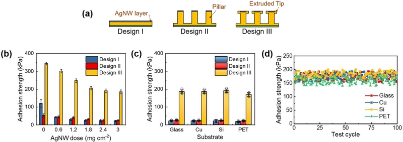
Adhesion characteristics of the self-interfacing transparent flexible heater. (a) Schematics of the flat (Design I), tip-free micropillar (Design II), and extruded-tip micropillar interfaces (Design III). (b) Adhesion strength as a function of AgNW dose. (c) Adhesion strength on different substrates at an AgNW dose of 0.6 mg cm-2. (d) Adhesion strength of Design III on glass, Cu, Si, and PET over 100 consecutive attachment–detachment cycles.
AgNW deposition reduces adhesion, although the extent of the reduction depends on the interface design. At 0.6 mg cm-2, the adhesion strength of Design I decreases sharply from 120 to 43 kPa, consistent with the AgNW coating interrupting direct contact between the initially continuous e-PUA surface and the substrate. Design II shows only a small initial change, from 52 to 45 kPa, because its contact is already confined to the pillar tops. The adhesion strength of Design III decreases more gradually, from 343 kPa without AgNWs to 300 kPa at 0.6 mg cm-2 and 184 kPa at 3.0 mg cm-2. Despite this reduction, Design III maintains substantially higher adhesion than the flat and tip-free pillar designs throughout the tested coating range. This retained adhesion suggests that contact is dominated by the extruded-tip regions, which remain exposed to the substrate and are less affected by increasing AgNW coverage. The same structural advantage is observed on glass, Cu, Si, and PET at an AgNW dose of 0.6 mg cm-2 (Fig. 2(c)). Designs I and II exhibit adhesion strengths of approximately 15–25 kPa, whereas Design III maintains values of approximately 170–190 kPa. The relatively small variation among the tested substrates indicates that the adhesion advantage of the extruded-tip structure is retained across different surface materials. In addition, a single Design III specimen for each substrate (n=1) was subjected to 100 consecutive attachment–detachment cycles on glass, Cu, Si, and PET under the same conditions as the single-cycle adhesion test. The adhesion strength remained stable without an evident decrease over repeated cycles (Fig. 2(d)).
The electrical and optical properties of the SFH vary with AgNW dose (Fig. 3(a)). Without AgNWs, the structure shows no measurable electrical conduction and exhibits an optical transmittance of 85.1%. At 0.6 mg cm-2, the sheet resistance is 7.35 × 10⁴ Ω sq-1, with a transmittance of 80.4%. Increasing the dose to 1.2 mg cm-2 reduces the sheet resistance to 157 Ω sq-1 while retaining 76.1% transmittance. Between 0.6 and 1.2 mg cm-2, the sheet resistance decreases by more than two orders of magnitude, consistent with the formation of a percolating AgNW network. At doses of 1.8, 2.4, and 3.0 mg cm-2, the sheet resistance decreases further to 63.5, 20.5, and 15.2 Ω sq-1, respectively, while the corresponding transmittance gradually decreases to 74.7%, 72.9%, and 70.5%.
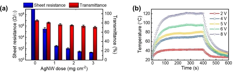
Electrical, optical, and thermal characteristics of the self-interfacing transparent flexible heater. (a) Sheet resistance and optical transmittance versus AgNW dose. (b) Surface temperature under applied voltages of 2–8 V.
Fig. 3(b) shows the voltage-dependent heating behavior of an SFH with a sheet resistance of approximately 15 Ω sq-1. The surface temperature increases with applied voltage, approaching 40, 70, 80, 95, and 120°C at 2, 4, 5, 6, and 8 V, respectively. At each voltage, the temperature gradually approaches a steady level as Joule heating balances heat loss to the surroundings. When the voltage is removed after 400 s, the heater cools toward room temperature.
3.3 Analysis of interfacial contact and heat transfer
Fig. 4 compares the Joule-heating responses of three heater contact methods and the condition of the substrate after detachment. Each configuration uses an optically transparent AgNW-coated heater with a sheet resistance of approximately 15 Ω sq-1. Au electrodes deposited on a glass substrate serve as electrical contacts, and the heater is positioned across the electrodes to complete the circuit (Fig. 4(a)). The surface beneath the glass substrate remains clearly visible through the central heater area in all three configurations, qualitatively demonstrating the optical transparency of the heater. In the first configuration, Ag paste forms a bonded electrical contact between the heater and the Au electrodes (Fig. 4(a-i)). In the second configuration, alligator clips mechanically press the heater against the electrodes, confining electrical contact to the clamped regions (Fig. 4(a-ii)). In the third configuration, the SFH attaches directly to the electrode-patterned substrate through its microstructured surface without Ag paste or sustained external clamping (Fig. 4(a-iii)).
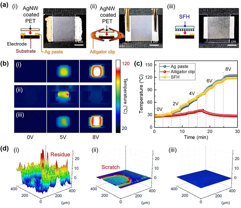
Comparison of heater–substrate contact configurations. (a) Schematics and photographs of contact using (i) Ag paste, (ii) alligator clips, and (iii) the self-interfacing heater. (b) Infrared thermographs at 0, 5, and 8 V. (c) Surface temperature during stepwise voltage increases from 0 to 8 V. (d) Substrate surface profiles after removal of each configuration.
The infrared thermographs show that the heating behavior depends strongly on the contact method (Fig. 4(b)). At 5 V, the Ag-paste-bonded heater produces a heated region across the active area, whereas the alligator-clip configuration generates a localized hot spot near the clamped region. The SFH exhibits a temperature distribution comparable to that of the Ag-paste-bonded reference. At 8 V, the Ag-paste and SFH configurations continue to heat across the active region, while the alligator-clip configuration no longer sustains heating. To quantitatively evaluate heating uniformity, we calculated the mean temperature, spatial standard deviation, and maximum-to-minimum temperature difference across the active heating region for the Ag-paste-bonded heater and SFH. At 5 V, the respective values were 77.0 ± 11.2°C and 66.3 ± 9.9°C, with temperature differences of 38.9 and 36.8°C. At 8 V, they were 112.9 ± 7.2°C and 112.4 ± 7.6°C, with temperature differences of 26.9 and 31.8°C, demonstrating comparable spatial heating uniformity. Temperature profiles under stepwise voltage increases show the same trend (Fig. 4(c)). The Ag-paste and SFH configurations exhibit similar temperature increases, with both reaching approximately 120°C at 8 V. By contrast, the alligator-clip configuration reaches 42°C at 5 V, at which point electrical contact is lost and the heater cools toward room temperature despite the subsequent voltage increase. The localized pressure imposed by the alligator clips confines electrical contact and current flow to small regions. Consequently, even a heater with an initially uniform structure develops localized Joule heating that can lead to loss of function.
Surface profilometry reveals distinct effects of the three contact methods after removal (Fig. 4(d)). The substrate used with Ag paste shows irregular surface features associated with residual paste (Fig. 4(d-i)), whereas the alligator-clip configuration leaves a scratch corresponding to the mechanically loaded region (Fig. 4(d-ii)). In contrast, the substrate contacted by the SFH retains a nearly flat profile, with no detectable residue or surface damage within the scanned area (Fig. 4(d-iii)). The plane-corrected Sa and Sq values after heater removal were 3.60 and 4.62 μm for the Ag-paste configuration, 0.295 and 0.435 μm for the alligator-clip configuration, and 0.00489 and 0.0112 μm for the SFH configuration, respectively. The substantially lower values for the SFH-contacted region are consistent with its nearly flat surface profile and indicate no detectable residue or surface damage within the examined area. The combined results show that the microstructured interface maintains electrical contact for Joule heating without additional bonding material or clamping.
The infrared thermographs and corresponding temperature profiles show the exposed heater surface temperature, and the persistence or loss of heating primarily indicates electrical-contact stability. Because the substrate-side temperature and heat flux were not independently measured, the experimental results do not directly quantify interfacial thermal coupling. Instead, the influence of interfacial separation on heater-to-substrate heat transfer was evaluated through finite-element analysis.
To examine heat flow within the microstructured interface beyond the macroscopic response observed in the experimental measurements, a finite-element model was used to compare the three interface geometries. The computational domain includes the heater, substrate, interfacial air region, and heat source, with symmetry conditions applied at the lateral boundaries (Fig. 5(a)). The same material properties and thermal conditions were applied to all three designs so that the effects of interface geometry could be compared.
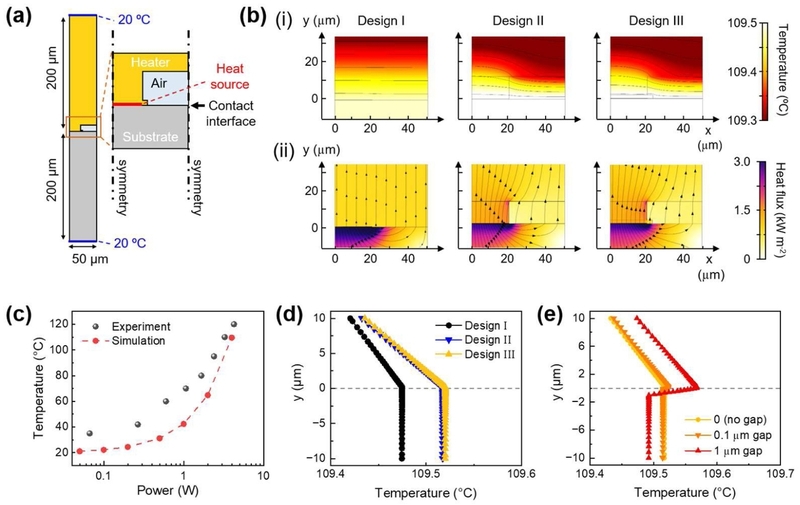
Numerical analysis of interfacial heat transfer. (a) Model geometry and thermal boundary conditions. (b) Simulated (i) temperature and (ii) heat-flux distributions for Designs I–III at an input power of 4 W. (c) Experimental and simulated temperatures of Design III as functions of input power. (d) Vertical temperature profiles of Designs I–III at an input power of 4 W. (e) Vertical temperature profiles of Design III with prescribed gaps of 0, 0.1, and 1 μm at an input power of 4 W.
Fig. 5(b) presents the steady-state temperature distribution (Fig. 5(b-i)) and heat-flux distribution (Fig. 5(b-ii)) for the three interface geometries. The same heat-generation rate and ideal heater–substrate contact condition are prescribed for all three designs. Because the substrate has a higher thermal conductivity than the polymer matrix, the generated heat is preferentially conducted toward the substrate. In Designs II and III, the internal air-filled cavities suppress heat conduction toward the upper polymer region, where solid conduction is confined to the reduced cross-sectional area of the micropillars. Consequently, these designs produce higher substrate-side temperatures than Design I. Designs II and III exhibit similar temperature and heat-flux distributions, indicating that the extruded tips have only a minor direct effect under the prescribed steady-state conditions. The calculated temperature for Design III also increases nonlinearly with input power, following a trend similar to that observed experimentally (Fig. 5(c)).
The vertical temperature profiles at an input power of 4 W show the same heat-partitioning behavior (Fig. 5(d)). Design I produces the lowest substrate-side temperature, whereas Designs II and III produce higher and nearly overlapping temperatures. The nearly identical temperature and heat-flux distributions of Designs II and III indicate that the extruded tips do not directly increase heat transfer under the assumed ideal-contact condition. Instead, their primary function is to enhance adhesion, maintain attachment after removal of the initial placement load, and limit interfacial separation, thereby preserving thermal coupling during operation. Because adhesion mechanics were not included, the ideal-contact model does not capture the experimentally observed adhesion difference between Designs II and III.
The influence of interfacial separation was examined separately for Design III by prescribing uniform gaps of 0, 0.1, and 1 μm at an input power of 4 W (Fig. 5(e)). These gaps provide simplified representations of local separation that may arise from bending-induced detachment, substrate curvature, or surface irregularities, rather than representing measured void dimensions in the fabricated SFH. Increasing the prescribed gap raises the heater-side temperature while lowering the substrate-side temperature, indicating that more heat is retained within the heater and less is transferred to the substrate. Although actual interfacial gaps are likely to be spatially nonuniform, this parametric analysis isolates how interfacial separation changes heat partitioning under the same heat-generation condition. Together with the adhesion enhancement observed in Fig. 2, these results suggest that the extruded-tip structure may support thermal coupling by limiting interfacial separation under practical contact conditions.
The ability of the SFH to maintain attachment on glass, Cu, Si, and PET suggests its potential use as a removable transparent heater for optical surfaces and temporary thermal-control interfaces where bonding residues or sustained mechanical clamping are undesirable. However, the present study is limited to proof-of-concept experiments on clean, nominally flat substrates under controlled laboratory conditions. Future work should therefore examine durability under practical operating conditions and directly quantify heat delivery to the target substrate.
4. CONCLUSIONS
This work presents a self-interfacing transparent flexible heater that integrates an AgNW heating network with extruded-tip micropillars. The microstructured interface maintains attachment without a separate bonding layer or sustained external compression and provides adhesion strengths up to ten times those of the flat and tip-free pillar designs. The heater reaches approximately 120°C at 8 V. Its heating distribution is comparable to that of an Ag-paste-bonded reference, whereas clip fixation produces localized heating and loses electrical contact at 5 V. The heater also detaches without the paste residues or clip-induced surface damage observed with the reference configurations. Finite-element analysis indicates that the microstructured cavities alter heat partitioning and that increasing interfacial separation reduces heat transfer to the substrate. Although the idealized model does not capture adhesion-dependent changes in physical contact, the combined results suggest that the extruded-tip interface preserves thermal coupling by maintaining heater–substrate contact and limiting interfacial separation.
Acknowledgments
This work was supported by a Research Grant of Pukyong National University(2024).
REFERENCES
-
H. Park, S. Kim, J. Lee, I. Lee, S. Bontapalle, Y. Na, et al., Organic flexible electronics with closed-loop recycling for sustainable wearable technology, Nat. Electron. 7 (2024) 39–50.
[https://doi.org/10.1038/s41928-023-01078-9]

-
S. Wu, Y. Hong, Y. Zhao, J. Yin, Y. Zhu, Caterpillarinspired soft crawling robot with distributed programmable thermal actuation, Sci. Adv. 9 (2023) eadf8014.
[https://doi.org/10.1126/sciadv.adf8014]
-
J. Park, H.-Y. Ahn, M. Seong, T. Kim, Y. Zhou, Y. Xu, et al., A Bioresorbable Neural Interface for On-Demand Thermal Pain Block, Adv. Funct. Mater. 36 (2026) e30035.
[https://doi.org/10.1002/adfm.202530035]
-
J. Zhou, Q. Zeng, Y. Liu, Y. Tao, Y. Sun, B. You, et al., Bioinspired dual-mode Janus film with optical adaptation for spatial thermal management and year-round energy saving, Nano Energy 134 (2025) 110580.
[https://doi.org/10.1016/j.nanoen.2024.110580]
-
Q. Liu, B. Tian, J. Liang, W. Wu, Recent advances in printed flexible heaters for portable and wearable thermal management, Mater. Horiz. 8 (2021) 1634–1656.
[https://doi.org/10.1039/D0MH01950J]
-
J. Li, Z. Xu, N. Li, K. Zhang, G. Xiong, M. Sun, et al., AIembodied multi-modal flexible electronic robots with programmable sensing, actuating and self-learning, Nat. Commun. 16 (2025) 8818.
[https://doi.org/10.1038/s41467-025-63881-6]
-
A. Georgopoulou, M. Aguiriano Calvo, L. Lucherini, S. Lee, J. Hughes, E. Amstad, Programmable somatosensory soft robots, Npj Flex. Electron. 10 (2026) 58.
[https://doi.org/10.1038/s41528-026-00558-0]
-
G. Kim, J.W. Lim, C. Yeon, T. Kim, H.C. Lee, S.J. Yun, Effective deicing of vehicle windows and thermal response of asymmetric multilayered transparent-film heaters, J. Alloys Compd. 774 (2019) 1092–1101.
[https://doi.org/10.1016/j.jallcom.2018.09.380]
-
Y. Kim, H.-J. Kim, J. Park, Y. Kim, S.K. Chung, J. Lee, Advanced visibility improvement based on a transparent heater for intelligent video surveillance systems, Measurement 260 (2026) 119778.
[https://doi.org/10.1016/j.measurement.2025.119778]
-
X. Duan, Y. Ding, R. Liu, Stability enhancement of silver nanowire-based flexible transparent electrodes for organic solar cells, Mater. Today Energy 37 (2023) 101409.
[https://doi.org/10.1016/j.mtener.2023.101409]
-
Y. Liu, X. Xu, Y. Wei, Y. Chen, M. Gao, Z. Zhang, et al., Tailoring Silver Nanowire Nanocomposite Interfaces to Achieve Superior Stretchability, Durability, and Stability in Transparent Conductors, Nano Lett. 22 (2022) 3784–3792.
[https://doi.org/10.1021/acs.nanolett.2c00876]
-
L. Hu, H.S. Kim, J.-Y. Lee, P. Peumans, Y. Cui, Scalable Coating and Properties of Transparent, Flexible, Silver Nanowire Electrodes, ACS Nano 4 (2010) 2955–2963.
[https://doi.org/10.1021/nn1005232]
-
Z. Zhang, H. Dong, Y. Liao, E.-X. Ding, L. Lv, H. Li, et al., Dry-transferred single-walled carbon nanotube thin films for flexible and transparent heaters, Surf. Interfaces 31 (2022) 101992.
[https://doi.org/10.1016/j.surfin.2022.101992]
-
J. Kang, H. Kim, K.S. Kim, S.-K. Lee, S. Bae, J.-H. Ahn, et al., High-Performance Graphene-Based Transparent Flexible Heaters, Nano Lett. 11 (2011) 5154–5158.
[https://doi.org/10.1021/nl202311v]
-
T. Guo, D. Zhou, S. Deng, M. Jafarpour, J. Avaro, A. Neels, et al., Rational Design of Ti3C2Tx MXene Inks for Conductive, Transparent Films, ACS Nano 17 (2023) 3733–3749.
[https://doi.org/10.1021/acsnano.2c11180]
-
J. Fan, Y.-C. Kuo, T. Yin, P. Guan, L. Meng, F. Chen, et al., One-Step Synthesis of Graphene-Covered Silver Nanowires with Enhanced Stability for Heating and Strain Sensing, ACS Appl. Mater. Interfaces 16 (2024) 39600–39612.
[https://doi.org/10.1021/acsami.4c06483]
-
S. Yu, X. Liu, H. Dong, X. Wang, L. Li, Flexible highperformance SnO2/AgNWs bilayer transparent conductors for flexible transparent heater applications, Ceram. Int. 47 (2021) 20379–20386.
[https://doi.org/10.1016/j.ceramint.2021.04.046]
-
K. Cui, J. Shan, Y. Xiao, Y. Liu, H. Zhang, X. Zhao, et al., Highly electrically stable Ag-Au core-shell nanowiresbased transparent conductive films, J. Alloys Compd. 1036 (2025) 181923.
[https://doi.org/10.1016/j.jallcom.2025.181923]
-
M. Seong, C. Park, J. Kim, M. Kim, J. Song, H.N. Kim, et al., Oxidation-resistant self-adhesive flexible transparent electrodes based on Ag–Au core-shell nanowires and heterogeneous microarchitectures, Mater. Today Nano 27 (2024) 100488.
[https://doi.org/10.1016/j.mtnano.2024.100488]
-
L. Wang, Y. Wang, F. Ning, H. Zhou, H. Wang, G.-S. Liu, Cross-Aligned, plasma-welded silver nanowire networks for high-performance flexible transparent electrodes, Surf. Interfaces 72 (2025) 107036.
[https://doi.org/10.1016/j.surfin.2025.107036]
-
J.-W. Zhao, R. Zhao, Y.-K. Huo, W.-L. Cheng, Effects of surface roughness, temperature and pressure on interface thermal resistance of thermal interface materials, Int. J. Heat Mass Transf. 140 (2019) 705–716.
[https://doi.org/10.1016/j.ijheatmasstransfer.2019.06.045]
-
H. Yüncü, Thermal contact conductance of nominaly flat surfaces, Heat Mass Transf. 43 (2006) 1–5.
[https://doi.org/10.1007/s00231-006-0087-9]
-
M. Kalin, B. Zugelj, M. Lamut, K. Hamouda, Elastic and plastic deformation of surface asperities and their loadcarrying mechanisms during the formation of a real contact area, Tribol. Int. 178 (2023) 108067.
[https://doi.org/10.1016/j.triboint.2022.108067]
-
M. Seong, I. Hwang, S. Park, H. Jang, G. Choi, J. Kim, et al., Enhanced Thermal Transport across Self-Interfacing van der Waals Contacts in Flexible Thermal Devices, Adv. Funct. Mater. 31 (2021) 2107023.
[https://doi.org/10.1002/adfm.202107023]