
Effect of Thermocouple Geometry on the Performance of MEMS Thermopile Infrared Sensors

ⓒ The Korean Sensors Society
This is an Open Access article distributed under the terms of the Creative Commons Attribution Non-Commercial License (https://creativecommons.org/licenses/by-nc/3.0/) which permits unrestricted non-commercial use, distribution, and reproduction in any medium, provided the original work is properly cited.
Abstract
This study investigates the influence of thermocouple layout on the performance of MEMS thermopile infrared (IR) sensors by comparing two sensor designs: a Line-type and a Core-type. Both sensors were fabricated on a 2 × 2 mm² suspended membrane using identical materials and fabrication processes, while differing in thermocouple geometry. The Line-type uniformly distributes thermocouples across the sensing area, whereas the Core-type concentrates the hot junctions in the central IR irradiation region and employs longer thermocouple legs. Under an incident IR power of 1.372 mW, the Core-type exhibited an output voltage of 119 mV, representing a 30.6% improvement over the Line-type (91.1 mV). Accordingly, the responsivity increased from 66.37 V/W to 86.75 V/W. However, the longer and narrower thermocouple structure increased the electrical resistance from 754.8 kΩ to 2.074 MΩ, resulting in higher noise voltage and a reduction in detectivity from 0.16 × 10⁸ to 0.14 × 108 cm·Hz1/2/W. These results demonstrate that thermocouple layout governs the trade-off between responsivity and detectivity, highlighting the importance of simultaneously optimizing thermoelectric response and electrical resistance in the design of high-performance MEMS thermopile IR sensors.
Keywords:
Infrared sensor, MEMS, Thermopile1. INTRODUCTION
Infrared (IR) sensors have been widely used in various applications, including non-dispersive infrared (NDIR) gas sensing, environmental monitoring, industrial safety, and non-contact medical diagnostics [1-4]. In particular, uncooled IR sensors, which operate without an additional cooling system, have attracted considerable attention owing to their low power consumption, compact size, and ease of system integration. Among various uncooled IR sensors, thermopile-based IR sensors offer several advantages, including self-powered operation, a broad spectral response, and compatibility with CMOS fabrication processes [5-7]. Thermopiles generate an output voltage proportional to the temperature difference between the hot and cold junctions based on the Seebeck effect. The output voltage can be expressed as
| (1) |
where N is the number of thermocouple pairs, αab is the Seebeck coefficient difference between the two thermoelectric materials a and b , and ΔT is the temperature difference between the hot and cold junctions. Therefore, increasing the thermocouple density within a limited device area is a common approach to improving sensor output performance. However, increasing the number of thermocouple pairs also increases the electrical resistance of the device, leading to higher Johnson noise. Consequently, thermopile IR sensors exhibit a trade-off between responsivity and noise [8,9].
However, the sensor performance is not determined solely by the number of thermocouple pairs. The thermocouple length and spatial arrangement also play important roles in establishing the effective temperature difference between the hot and cold junctions. In general, longer thermocouples extend the heat conduction path and increase the thermal resistance between the hot and cold junctions, thereby facilitating a larger temperature difference. However, the increased leg length also increases the electrical resistance, resulting in higher Johnson noise [10,11]. Furthermore, positioning the hot junctions in higher-temperature regions can enhance the effective temperature difference and thermoelectric response [12]. Therefore, in addition to the number of thermocouple pairs, both the thermocouple length and layout should be considered in the design of high-performance thermopile IR sensors.
Recent studies have investigated various approaches to enhance MEMS thermopile performance by optimizing thermocouple configurations, heat conduction, and infrared absorption, thereby improving responsivity and detectivity [13-15]. In this study, two different thermocouple layouts, referred to as the Line and Core types, were designed and fabricated within the same device area of 2 × 2 mm2. Unlike conventional radial thermopile structures, both layouts were designed to distribute thermocouples across the entire membrane while differing in their number, length, and arrangement. The fabricated devices were evaluated under identical measurement conditions by comparing their output voltage, responsivity, and detectivity to investigate the effect of thermocouple layout on the performance of thermopile IR sensors.
2. EXPERIMENTAL
2.1 Layout design of thermopile IR sensors
Fig. 1 shows the layouts of the designed Line-type and Core-type MEMS thermopile IR sensors. Both types have the same device size (2 × 2 mm2). Unlike conventional radial thermopile structures, both layouts were designed with thermocouples distributed across the entire sensing area.
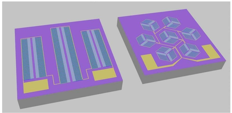
Layouts of the designed Line-type (left) and Core-type (right) thermopile IR sensors.
The Line-type was designed to achieve a high thermocouple density by repeatedly arranging relatively short thermocouple legs. In contrast, the Core-type features hot junctions that are relatively concentrated in the central IR irradiation region and employs longer thermocouple legs. In addition, to accommodate longer thermocouple legs while maintaining as many thermocouple pairs as possible within the limited device area, the thermocouple leg width was reduced from 10 μm in the Line-type to 5 μm in the Core-type.
The Line-type and Core-type were designed with 266 and 231 thermocouple pairs, respectively, and the thermocouple leg lengths were 200 μm and 250 μm. The main design parameters of the two types are summarized in Table 1.

Design parameters of the Line-type and Core-type MEMS thermopile IR sensors.
2.2 Fabrication of thermopile IR sensors
Fig. 2 illustrates the fabrication process of the MEMS thermopile IR sensor. The devices were fabricated using a standard MEMS process. A low-stress silicon nitride (LSN) layer was deposited on a silicon substrate by low-pressure chemical vapor deposition (LPCVD) to provide electrical insulation and mechanical support.
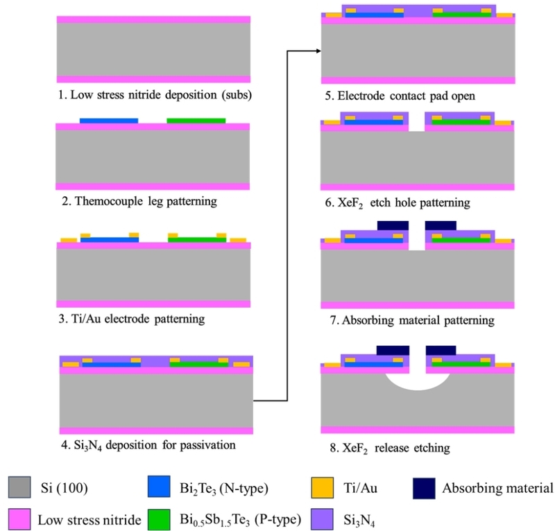
Fabrication process of thermopile IR sensors.
BiTe-based materials were employed because of their high Seebeck coefficient and low thermal conductivity at room temperature, which are advantageous for uncooled MEMS thermopile applications [16-18]. Then, n-type Bi2Te3 and p-type Bi0.5Sb1.5Te3 thermoelectric thin films were sequentially deposited by RF magnetron sputtering and patterned using a lift-off process. Ti/Au electrodes were then deposited by electron-beam evaporation and patterned using a lift-off process to electrically connect all thermocouples in series.
A SiNx passivation layer was subsequently deposited by plasma-enhanced chemical vapor deposition (PECVD) to protect the thermoelectric materials. The contact pad regions were opened by reactive ion etching (RIE) of the SiNx passivation layer. Front-side etch holes were formed by RIE. SU-8 was selected as the IR absorbing layer because of its low thermal conductivity, intrinsic absorption in the mid-IR region, and compatibility with conventional photolithography [18-20]. Subsequently, the SU-8 2002 absorbing layer was patterned over the hot-junction region by photolithography. Finally, a thermally isolated membrane structure was fabricated by isotropic silicon etching using XeF2 through the front-side etch holes.
2.3 Measurement set-up
The fabricated thermopile sensors were characterized under identical IR irradiation conditions using the measurement system shown in Fig. 3. To minimize external environmental interference, the measurements were conducted in a chamber equipped with a gold-plated optical waveguide, which focused the IR radiation onto the center of the sensor, producing an irradiation spot of approximately 1 mm in diameter. An IR light source (International Light) was periodically modulated with a 1 s on/off cycle. The output signal of the thermopile sensor in response to the incident IR radiation was amplified by a factor of 10 using a differential amplifier (NF Corporation, Model 5307). The amplified output signal was then measured using an oscilloscope (Keysight Technologies, MSO-X 4104A). All output voltages reported in this study were corrected for the amplifier gain (×10).
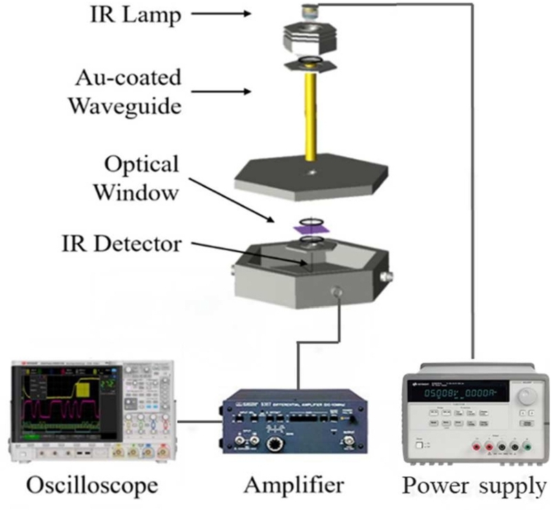
Schematic of the measurement set-up for thermopile IR sensor characterization.
3. RESULTS AND DISCUSSION
Fig. 4 shows the stereo microscope images and LV-SEM images of the fabricated Line and Core thermopile IR sensors. Both structures were successfully fabricated according to the designed layouts. The thermocouples and Ti/Au interconnects were continuously formed without any observable disconnections.
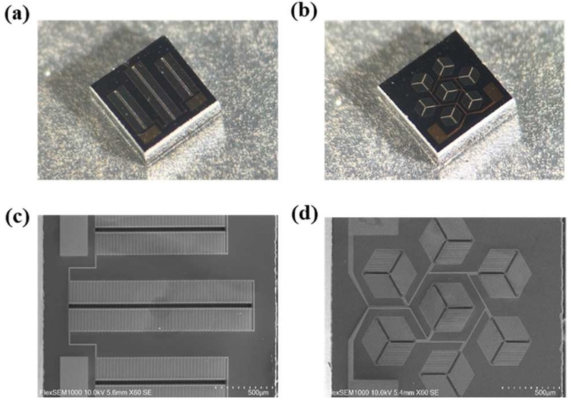
Fabricated thermopile IR sensors. (a,b) Stereo microscope images of the Line-type and Core-type; (c,d) Corresponding LV-SEM images.
3.1 Output voltage and responsivity characteristics
Fig. 5 shows the output voltage responses of the Line and Core types under periodic IR irradiation with a 1 s on/off cycle. Both structures exhibited repetitive output voltage variations in response to the IR irradiation, showing similar response characteristics in each cycle, which confirms stable operation and good repeatability.
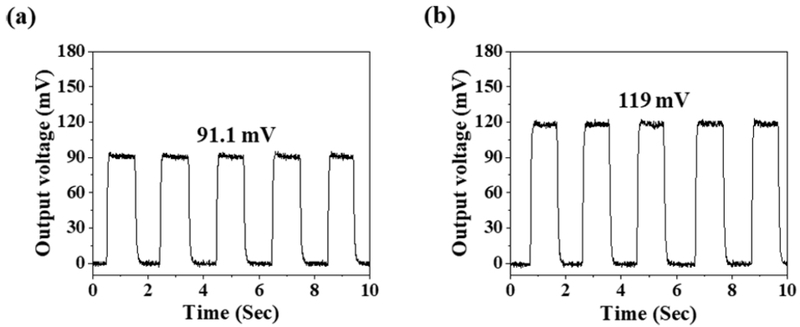
Output voltage responses of the (a) Line-type and (b) Core-type MEMS thermopile IR sensors.
The average output voltage was measured to be 91.1 mV for the Line-type and 119 mV for the Core-type. The Core-type exhibited an approximately 30.6% higher output voltage than the Line-type. This improvement is attributed to the combined effects of the more centrally concentrated hot junctions and the longer thermocouple legs of the Core-type. Longer thermocouple legs can increase the temperature difference between the hot and cold junctions by raising the thermal resistance along the heat conduction path, while positioning hot junctions in higher-temperature regions can further enhance the thermoelectric response [11,12].
The voltage responsivity (Rv) was calculated as the ratio of the output voltage to the incident IR power:
| (2) |
where P0 is the incident IR power. The incident IR power measured at the sensor position using a power meter (Thorlabs, S401C) was 1.372 mW. Accordingly, the responsivities of the Line-type and Core-type were calculated to be 66.37 V/W and 86.75 V/W, respectively. Because the same incident IR power was applied to both structures, the responsivity exhibited the same trend as the output voltage.
These results indicate that increasing the number of thermocouple pairs alone does not necessarily improve the output characteristics, and that the thermocouple arrangement should also be considered. In particular, placing the hot junctions within the central IR irradiation region plays an important role in enhancing the thermoelectric response.
Fig. 6 shows the device-to-device reproducibility of the fabricated Line-type and Core-type MEMS thermopile IR sensors. For each sensor type, three devices with the same design dimensions listed in Table 1 were measured under identical IR irradiation conditions (n = 3). Each data point represents the average output voltage of an individual device, with the error bars indicating the minimum and maximum. Both sensor configurations exhibited highly consistent output voltages with only small variations among the devices, indicating good fabrication reproducibility and stable sensor performance [18].
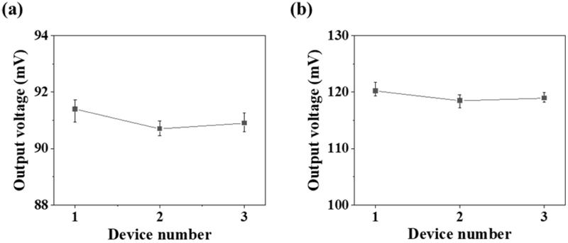
Device-to-device reproducibility of the (a) Line-type and (b) Core-type MEMS thermopile IR sensors.
3.2 Noise voltage and detectivity characteristics
The measured electrical resistance was 754.8 kΩ for the Line-type and 2.074 MΩ for the Core-type. The significantly higher resistance of the Core-type is attributed to its longer and narrower thermocouple legs.
Johnson noise was considered to be the dominant contribution to the detector noise voltage, unoise, as reported for thermopile IR sensors [5]. Accordingly, unoise was calculated using
| (3) |
where k is the Boltzmann constant, R0 is the electrical resistance of the detector, T0 is the ambient temperature, and Δf is the measurement bandwidth, which was taken as 1 Hz. The calculated unoise values were 0.111 μV and 0.185 μV for the Line-type and Core-type, respectively. Owing to its higher electrical resistance, the Core-type exhibited approximately 1.7 times higher unoise than the Line-type. Since Johnson noise is proportional to the square root of the electrical resistance, the increased resistance of the Core-type resulted in higher thermal noise. Therefore, structural modifications intended to improve the output voltage should also be evaluated for their influence on the noise characteristics.
The detectivity was calculated using
| (4) |
where Ad is the sensing area. The calculated detectivities were 0.16 × 108 cm·Hz1/2/W for the Line-type and 0.14 × 108 cm·Hz1/2/W for the Core-type. Although the Core-type exhibited higher output voltage and responsivity, the increased electrical resistance resulted in higher Johnson noise, leading to a lower detectivity. In contrast, the Line-type exhibited a lower responsivity but achieved a higher detectivity because of its lower electrical resistance and reduced Johnson noise.
Fig. 7 summarizes the trade-off between responsivity and detectivity for the Line-type and Core-type thermopile IR sensors. These results demonstrate that improving the output voltage and responsivity does not guarantee better overall sensor performance. Although the longer thermocouple legs of the Core-type enhanced the thermoelectric response, they also increased the electrical resistance, resulting in higher Johnson noise and consequently lower detectivity. Therefore, optimizing MEMS thermopile IR sensors requires a careful balance between responsivity and electrical resistance to maximize overall sensor performance.
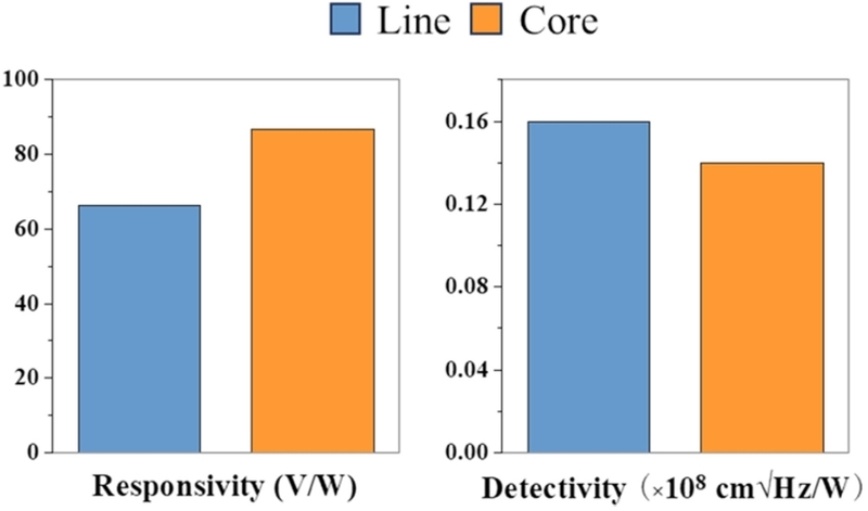
Comparison of the responsivity and detectivity of the Line-type and Core-type MEMS thermopile infrared sensors.
Compared with representative MEMS thermopile IR sensors reported in previous studies [8,11,12], the Line-type and Core-type showed higher responsivity but lower detectivity. Although the device structures and measurement conditions differ among the studies, the comparison shows the trade-off between responsivity and detectivity in the present devices.
4. CONCLUSIONS
In this study, Line-type and Core-type MEMS thermopile infrared sensors were designed and fabricated to investigate the effect of thermocouple arrangement on sensor performance. Although the Core-type contained fewer thermocouple pairs than the Line-type, concentrating the hot junctions in the central infrared irradiation region and employing longer thermocouple legs resulted in a 30.6% higher output voltage (119 mV) and a higher responsivity (86.75 V/W) than those of the Line-type (91.1 mV and 66.37 V/W, respectively). However, the longer and narrower thermocouple legs significantly increased the electrical resistance, resulting in higher noise voltage and a reduction in detectivity from 0.16 × 108 cm·Hz1/2/W for the Line-type to 0.14 × 108 cm·Hz1/2/W for the Core-type.
These results demonstrate that thermocouple arrangement plays a critical role in determining the trade-off between responsivity and detectivity. Therefore, improving the performance of MEMS thermopile infrared sensors requires optimization of the thermocouple geometry by considering not only responsivity but also electrical resistance and noise characteristics.
Acknowledgments
This study is a 2024 SME Technology Innovation Development Export-Oriented (Tech-Bridge) R&D project of the Small and Medium Business Technology Information Promotion Agency (SME Technology Innovation Development Institute), and is a study on Development of 8-Channel Total Organic Carbon (TOC) Measuring Device for Regular Monitoring of Water Quality of Waste Water and Process Water (RS-2024-00469087). This work was supported by the Technology development Program (RS-2025-25461651) funded by the Ministry of SMEs and Startups (MSS, Korea). This study was conducted with the support of the Korea Institute of Industrial Technology as “Development and commercialization for clean hydrogen production/storage and CO2 monitoring system in the field of industrial complex (Kitech EH-26-0008)”.
REFERENCES
-
N. Argirusis, A. Achilleos, N. Alizadeh, C. Argirusis, G. Sourkouni, IR sensors, related materials, and applications, Sensors 25 (2025) 673.
[https://doi.org/10.3390/s25030673]

-
X. Yu, Y. Ji, X. Shen, X. Le, Progress in advanced infrared optoelectronic sensors, Nanomaterials 14 (2024) 845.
[https://doi.org/10.3390/nano14100845]
-
J.A. Sobrino, F. Del Frate, M. Drusch, J.C. Jiménez-Muñoz, P. Manunta, A. R egan, R eview of thermal infrared applications and requirements for future high-resolution sensors, IEEE Trans. Geosci. Remote Sens. 54 (2016) 2963–2972.
[https://doi.org/10.1109/TGRS.2015.2509179]
-
F. Hou, Y. Zhang, Y. Zhou, M. Zhang, B. Lv, J. Wu, Review on infrared imaging technology, Sustainability 14 (2022) 11161.
[https://doi.org/10.3390/su141811161]
-
D. Xu, Y. Wang, B. Xiong, T. Li, MEMS-based thermoelectric infrared sensors: A review, Front. Mech. Eng. 12 (2017) 557–566.
[https://doi.org/10.1007/s11465-017-0441-2]
-
C. Escriba, E. Campo, D. Estève, J.Y. Fourniols, Complete analytical modeling and analysis of micromachined thermoelectric uncooled IR sensors, Sens. Actuators A Phys. 120 (2005) 267–276.
[https://doi.org/10.1016/j.sna.2004.11.027]
-
E. Moisello, M. Vaiana, M.E. Castagna, G. Bruno, P. Malcovati, E. Bonizzoni, An integrated micromachined thermopile sensor with a chopper interface circuit for contact-less temperature measurements, IEEE Trans. Circuits Syst. I Regul. Pap. 66 (2019) 3402–3413.
[https://doi.org/10.1109/TCSI.2019.2928717]
-
T. Liang, Y. Guan, C. Lei, X. Wu, Y. Bai, J. Xiong, et al., Design and fabrication of a low-cost thermopile infrared detector, Micromachines 12 (2021) 1134.
[https://doi.org/10.3390/mi12091134]
-
D. Vashaee, Thermoelectric infrared detectors: Design, fabrication, and performance assessment, J. Semicond. 45 (2024) 122304.
[https://doi.org/10.1088/1674-4926/24060011]
-
Z. Yang, G. Xu, S. Chen, J. Feng, X. Chen, Y. Ma, et al., Fast response infrared detector using a radially distributed dual-layer thermopile, IEEE Sens. J. 24 (2024) 1233–1244.
[https://doi.org/10.1109/JSEN.2023.3329154]
-
Y. Xia, X. Meng, Y. Lv, X. Han, Y. Tang, W. Jiang, et al., Development of a novel radially-distributed spiral bilayer thermopile infrared sensor with enhanced responsivity, Microsyst. Nanoeng. 12 (2026) 169.
[https://doi.org/10.1038/s41378-026-01278-1]
-
Y. Guan, C. Lei, T. Liang, Y. Bai, X. Wu, J. Xiong, et al., Design, preparation and characterization of a double-ended symmetric MEMS thermopile with adiabatic grooves, Infrared Phys. Technol. 122 (2022) 104078.
[https://doi.org/10.1016/j.infrared.2022.104078]
-
S. Ben Mbarek, N. Alcheikh, M.I. Younis, Recent advances on MEMS based infrared thermopile detectors, Microsyst. Technol. 28 (2022) 1751–1764.
[https://doi.org/10.1007/s00542-022-05306-8]
-
C. Lei, Y. Guan, T. Liang, X. Wu, Y. Bai, M. Gong, et al., Micromachined infrared thermopile detector based on a suspended film structure, Photonic Sens. 13 (2023) 230309.
[https://doi.org/10.1007/s13320-023-0682-0]
-
Y. He, Y. Wang, T. Li, Simultaneously controlling heat conduction and infrared absorption with a textured dielectric film to enhance the performance of thermopiles, Microsyst. Nanoeng. 7 (2021) 36.
[https://doi.org/10.1038/s41378-021-00264-z]
-
J.R. Sootsman, D.Y. Chung, M.G. Kanatzidis, New and old concepts in thermoelectric materials, Angew. Chem. Int. Ed. 48 (2009) 8616–8639.
[https://doi.org/10.1002/anie.200900598]
-
E.M.F. Vieira, J. Figueira, A.L. Pires, J. Grilo, M.F. Silva, A.M. Pereira, et al., Enhanced thermoelectric properties of Sb₂Te₃ and Bi₂Te₃ films for flexible thermal sensors, J. Alloys Compd. 774 (2019) 1102–1116.
[https://doi.org/10.1016/j.jallcom.2018.09.324]
-
U. Han, J. Lee, Y. Ha, K. Kim, G. Park, D.G. Jung, et al., Impact of thermocouple geometry on performance in MEMS thermopile IR sensors, Jpn. J. Appl. Phys. 65 (2026) 08SP22.
[https://doi.org/10.35848/1347-4065/ae5c0e]
- Kayaku Advanced Materials, SU-8 2000 Permanent Negative Epoxy Photoresist, Technical Data Sheet, 2020.
-
C.G. Mattsson, K. Bertilsson, G. Thungström, H.-E. Nilsson, H. Martin, Thermal simulation and design optimization of a thermopile infrared detector with an SU-8 membrane, J. Micromech. Microeng. 19 (2009) 055016.
[https://doi.org/10.1088/0960-1317/19/5/055016]