InGaZnO Thin-Film Transistor-based pH Sensor with Parylene-C Gate Dielectric
This is an Open Access article distributed under the terms of the Creative Commons Attribution Non-Commercial License(https://creativecommons.org/licenses/by-nc/3.0/) which permits unrestricted non-commercial use, distribution, and reproduction in any medium, provided the original work is properly cited.
Abstract
The measurement of pH is of significant importance in chemistry, life sciences, and environmental monitoring. Unlike conventional pH sensors that utilize glass electrodes, thin-film transistor (TFT)-based pH sensors offer distinct advantages, including enhanced response speed and additional circuit functions. In this study, we developed a pH sensor that incorporates biocompatible parylene-C as both the substrate and sensing layer, thereby enhancing flexibility, transparency, and biological compatibility. We conducted tests to measure the voltage–current characteristics of the pH solutions and assessed their performance in terms of drift and hysteresis. Using InGaZnO (IGZO) as the channel material, our pH sensor demonstrated an average sensitivity of approximately 82 mV/pH, albeit with certain drift limitations. The initial pH measurements exhibited good reversibility over time. IGZO- and parylene-C-based TFT pH sensors are well suited for various applications, including wearable health monitoring, owing to their flexibility and biocompatibility.
Keywords:
pH sensor, Parylene-C, IGZO, Microfluidic channel1. INTRODUCTION
Measuring pH is crucial in various fields, such as chemistry, life sciences, environmental monitoring, and health diagnostics. pH is an indicator of the acidity or alkalinity of a solution, and precise measurements are essential for a wide range of experiments and industrial processes [1-3]. Conventional pH measurement methods using a pH meter employ a glass electrode, which has several drawbacks, such as handling difficulties, slow response times, and miniaturization challenges [4-7]. These limitations are particularly problematic for real-time monitoring and portabledevice applications. To overcome these challenges, thin-film transistor (TFT)-based pH sensors have attracted considerable attention. TFT-based pH sensors offer advantages such as rapid response, small size, ease of fabrication, low production costs, and potential for fabrication on flexible substrates [8-10]. They can potentially replace glass electrode pH meters used in chemicals and biosensors [11]. In this study, we developed a TFT-based pH sensor using a flexible and biocompatible semiconductor fabrication process. Specifically, we utilized parylene-C to fabricate a pH sensor with transparent and flexible characteristics. Although pH sensors using parylene-C as the sensing layer have been developed, these sensors use PCB substrates and exhibit low sensitivity in the 15–25 mV/pH range [12,13]. In this research, both the substrate and the sensing layer were made of parylene-C to enhance the applicability of the sensor. Using parylene-C as a substrate enhances flexibility and transparency, expanding its potential for bioadhesive applications and pH sensors in health monitoring. In addition, indium gallium zinc oxide (IGZO) was utilized as the TFT channel material to enhance the sensitivity, utilizing its excellent electrical properties. [11,14,15]. The current–voltage characteristics in pH buffer solutions were measured to assess changes in the current properties and evaluate the sensor's drift and hysteresis performance through repeated measurements. The results indicated higher sensitivity compared to existing sensors but also revealed limitations due to drift and other factors. To compensate for the initial drift, the drift was measured repeatedly over time. It is anticipated that health monitoring through sweat could be enabled with appropriate wireless functions [16]. This integration would support real-time data transmission and analysis, facilitating effective health monitoring.
2. EXPERIMENTAL
2.1 Structure of the pH Sensor
The structure of the sensor, illustrated in Fig. 1 (a), features a staggered top-gate design, in which the top gate is replaced by a reference electrode. The sensor surface in contact with both the substrate and solution is coated with parylene-C, which is known for its transparent and flexible properties. Parylene C significantly enhances the durability of the sensor owing to its excellent chemical stability. IGZO serves as the channel material, ensuring transparency and maintaining flexibility in nonmetal components after the device is released from the silicon wafer.
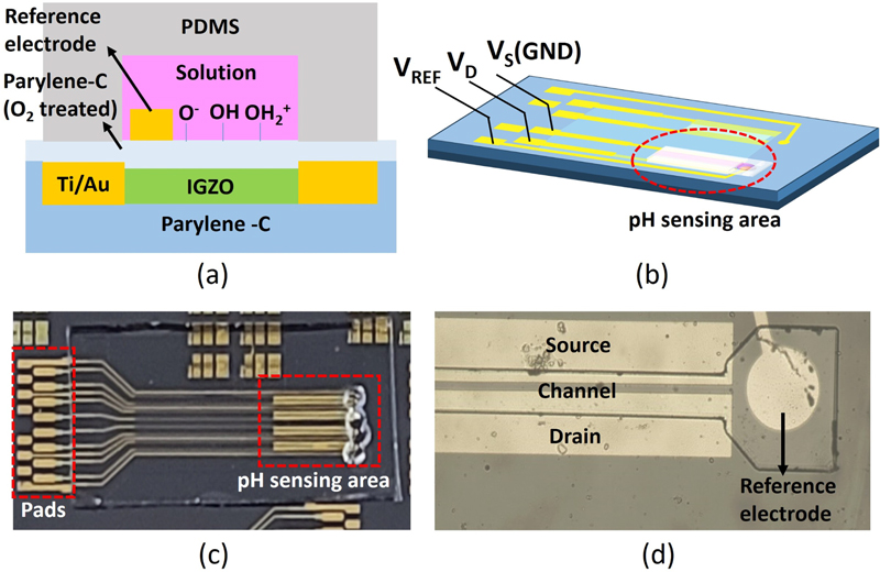
(a) Cross-sectional structure of the pH sensor; (b) 3D schematic of the pH sensor; (c) photographed image of the pH sensor; and (d) optical microscopic image of the sensing area, marked with a red circle in (b).
Fig. 1 (c) shows an image of the device on a silicon wafer with an integrated microfluidic channel. The incorporation of a microfluidic channel ensures that the solution flows exclusively through this area, preventing the formation of interfacial potentials between the source, drain, and substrate surfaces and the solution, which otherwise influence the potential of the solution [17].
2.2 Fabrication of the pH sensor
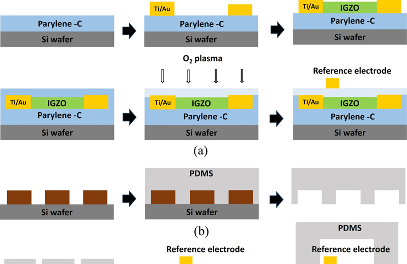
Fig. 2 (a) depicts the method used for the fabrication of the pH sensor. First, a 10 μm layer of parylene-C is coated onto a 4-inch Si wafer using a chemical vapor deposition (CVD) process to create the substrate. All the metal electrodes are made of Ti/Au (25/50 nm) and patterned using a lift-off method. Titanium is used to increase adhesion, and gold is used to prevent potential changes in the reference electrode caused by the solution because gold does not form -OH groups [18]. After depositing the source and drain electrodes, IGZO is deposited as the channel material using RF sputtering with an Ar:O2 ratio of 9:0.7 at 5 mTorr and 150 W, resulting in a thickness of approximately 30 nm. For the sensing layer, parylene-C is similarly deposited to a thickness of 250 nm, followed by O2 plasma treatment (100 W, 30 s) to form -OH groups on the surface, changing it from hydrophobic to hydrophilic to enhance sensitivity. Finally, the reference electrode is deposited and patterned. Fig. 2 (b) illustrates the microfluidic channel fabrication process. SU-8 50 is patterned on a Si wafer to create a mold. Polydimethylsiloxane (PDMS) is prepared by mixing the Sylgard 184 base and crosslinker in a 10:1 ratio. The mixture is poured into a mold and cured in a vacuum oven at 90 °C for 90 min before peeling off to complete the microfluidic channel. The PDMS microfluidic channel has a width of 5000 μm, length of 30 μm, and height of approximately 2 mm. After inlet formation in the PDMS, the TFT device and microfluidic channel are aligned using an optical microscope (Fig. 2 (c)).
3. RESULTS AND DISCUSSIONS
3.1 Analysis of pH Sensor Characteristics
To confirm the characteristics of the fabricated parylene-C-based pH sensor, the drain current (ID) and current through the reference electrode (IREF) were measured at pH 4, 7, and 10. After measurement in the pH solutions, the parylene-C surface was rinsed in deionized (DI) water for 10 min and dried using an N2 gun to restore its condition. The results depicted in Fig. 3 (a) show a decreasing threshold voltage trend at lower pH levels. This trend was attributed to the interaction between the hydrogen ions in the solution and the O2 plasma-treated parylene-C surface. At lower pH levels, a higher concentration of hydrogen ions results in the formation of more –OH2+ groups on the surface. This increase in the number of –OH2+ groups enhances the effective gate voltage (VG,eff), thereby reducing the threshold voltage. The effective gate voltage changes according to Eqs. (1) and (2) [11]. The surface potential (ψo) of the sensing layer changes with pH, as shown in Eq. (2). Here, α is a sensitivity parameter that ranges from 0 to 1, varying based on the surface properties of the material.
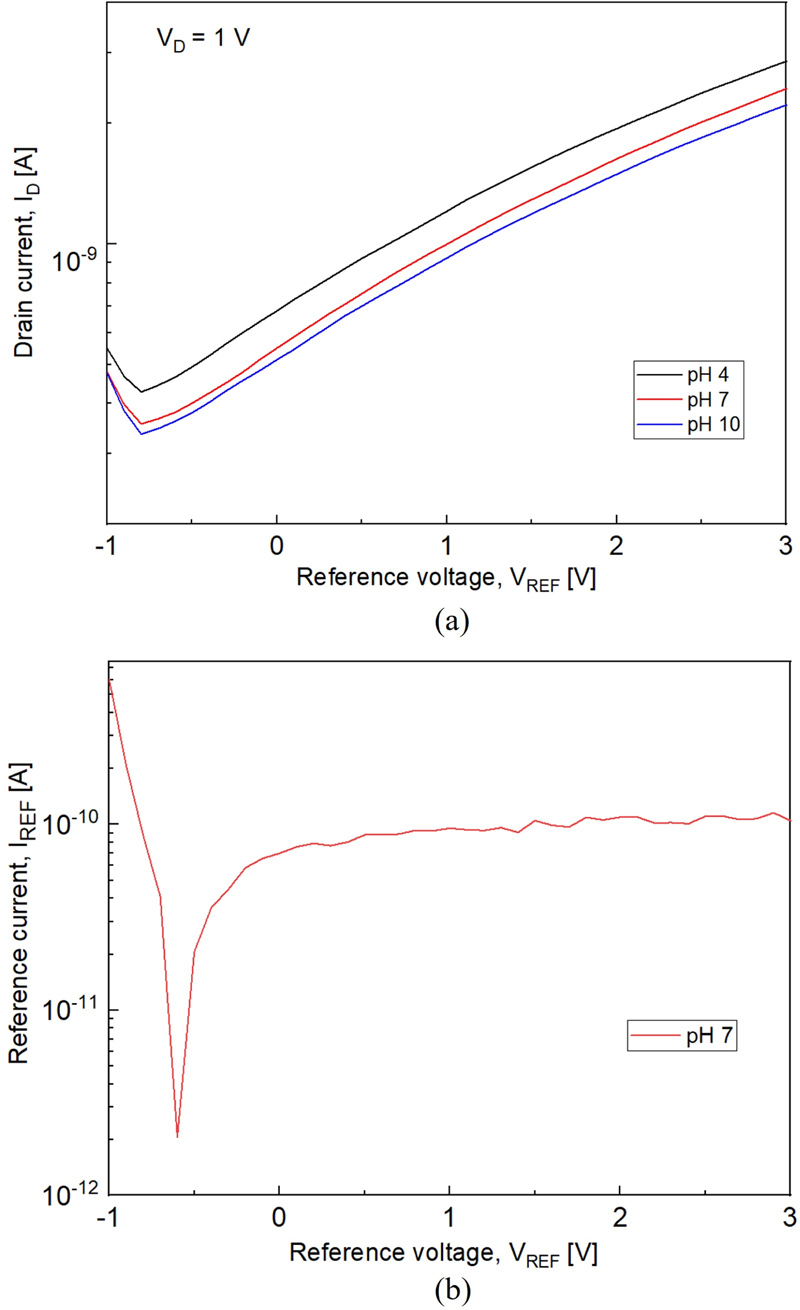
(a) pH sensing characteristics of the pH sensor; and (b) reference current (IREF) graph at pH 7 (IREF equals leakage current).
| (1) |
| (2) |
To verify whether the change in ID was due to the leakage current through the reference electrode, the leakage current (IREF) was measured. The results showed that the magnitude of the IREF was considerably smaller than that of the ID. Therefore, it was confirmed that the changes in ID were not caused by the leakage current.
Changes in the threshold voltage were observed during initial measurements owing to electron trapping in the gate insulator, parylene-C, or at the insulator-channel interface traps [16]. To identify the drift component, current measurements were conducted on a different device at pH 7 five times at 1-min intervals, for a total of four sets. Prior to each set of measurements, the device was rinsed with DI water for 10 min and dried using an N2 gun, as previously described. The VREF value at ID of 10 nA gradually decreased during the first set of repeated measurements. However, from the second set of repeated measurements onward, the drift component of VREF noticeably reduced, as shown in Fig. 4 (a). However, the subsequent observations continued to exhibit drift values caused by temperature fluctuations and exposure to moisture and oxygen in the atmosphere [19,20]. The values are listed in Table 1. These measurements suggest that electron trapping was completed during the first set of repeated measurements or that surface changes occurred during the subsequent DI water rinsing and N2 drying processes, leading to a reduction in the drift component. Figs. 4 (b) and (c) show the results measured for different devices without considering the initial drift.
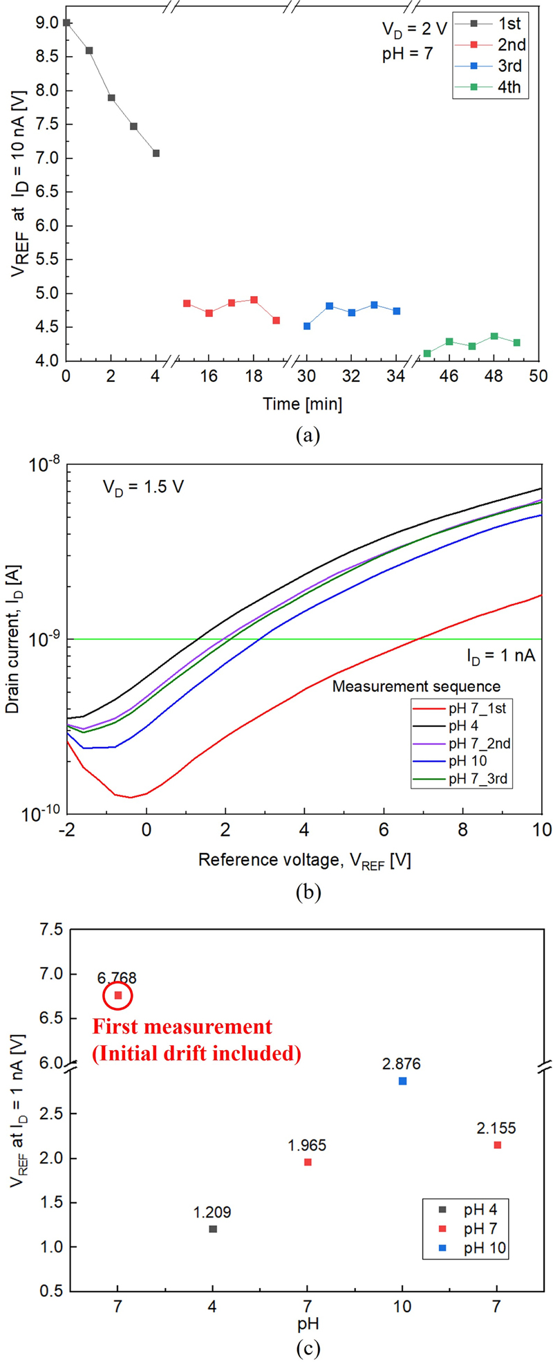
(a) Drift test over time measured at pH 7. ‘1st’ through ‘4th’ correspond to four sequential sets of five current measurements at pH 7, with rinsing between each set; (b) pH sensing characteristics of the pH sensor in a pH cycle 7-4-7-10-7 (‘1st,’ ‘2nd,’ and ‘3rd’ measurements correspond to the three sequential measurements at pH 7); and (c) VREF graph at ID = 1 nA without considering the initial drift.
As illustrated in Fig. 4 (a), the first measurement value differs from the subsequent measurements, owing to the previously described initial drift effect. To ensure accuracy in sensitivity verification, data from measurements taken after one cycle at pH 7 were used to calculate the sensitivity in a stabilized state.
3.2 Reliability Analysis of the pH Sensor
To evaluate the reliability of the fabricated parylene-C-based pH sensor, hysteresis and sensitivity were measured by varying the pH values in the sequence 7-4-7-10-7 (Fig. 5 (a)). After measurements in the pH buffer solutions, the sensor was rinsed in DI water for 10 min and dried using an N2 gun, similar to the procedure shown in Fig. 3. Consequently, Figs. 4 and 5 exhibit different drift tendencies owing to the different methods employed for handling the initial drift. In Fig. 4, the data include the initial drift, whereas in Fig. 5, the initial drift caused by the interface traps was corrected by performing five repeated measurements in a pH 7 solution, as shown in Fig. 4 (a), and then focusing on the sensor's performance after stabilization. Hysteresis measurements were performed at VD = 1 V and ID = 1 nA. The results indicate an average hysteresis of 73.5 mV at pH 7. The sensitivity of the sensor was calculated using Eq. (3).
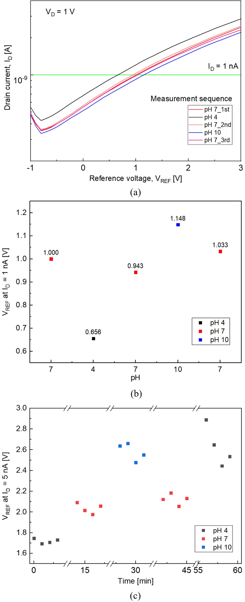
(a) pH sensing characteristics of the pH sensor in a pH cycle 7-4-7-10-7; (b) VREF graph at ID = 1 nA; and (c) Time-dependent sensing characteristics of the pH sensor in a pH cycle 4-7-10-7-4.
| (3) |
The calculated results, shown in Fig. 5 (b), indicate an average sensitivity of 82 mV/pH. We note that the sensitivity might have been overestimated owing to the presence of drift and hysteresis components.
Fig. 5 (c) shows the time-dependent sensing characteristics of the pH sensor. The measurement was conducted four times at 1-min intervals, following the pH sequence of 4-7-10-7-4. The sensor demonstrates good reversibility until the second pH 7 measurement, after which the VREF value increased in subsequent measurements. This increase was attributed to potential leakage at the source and drain sides, possibly caused by weak adhesion in the microfluidic channel or damage to parylene-C during the measurements. However, despite the presence of drift and hysteresis components, the pH sensor successfully detected and measured pH changes. The long-term operational stability could be further enhanced by adjusting the thickness of the parylene-C used as the sensing layer, optimizing the O2 plasma treatment conditions, and increasing the adhesion between the PDMS microfluidic channel and Si wafer through O2 plasma treatment on the PDMS surface to prevent detachment during measurement or rinsing.
4. CONCLUSIONS
In this study, a TFT-based pH sensor was developed using parylene-C and IGZO. The sensor incorporated a microfluidic channel to exclusively control the flow of the solution through the designated area. The voltage–current characteristics of the sensor confirmed its high sensitivity through experimental validation. Additionally, an analysis of the sensor's drift characteristics indicated that the initial drift attributed to electron trapping decreased with repeated measurements. The fabricated sensor exhibited a hysteresis of 73.5 mV at pH 7 and an average sensitivity of 82 mV/pH. Although the pH measurements over time demonstrated good reversibility, long-term measurements exhibited limitations. Future research should focus on minimizing drift and hysteresis to further enhance the sensor’s stability. The proposed sensor has potential applications in real-time health monitoring by leveraging additional features, such as wireless communication.
Acknowledgments
This work was supported by the 2023 Sabbatical Year Research Grant from the University of Seoul. It is also partly supported by Korea Institute for Advancement of Technology (KIAT) grant funded by the Korea Government (MOTIE) (P0017011, HRD Program for Industrial Innovation).
References
-
M. I. Khan, K. Mukherjee, R. Shoukat, and H. Dong, “A review on pH sensitive materials for sensors and detection methods”, Microsyst. Technol., Vol. 23, pp. 4391-4404, 2017.
[https://doi.org/10.1007/s00542-017-3495-5]

-
M. T. Ghoneim, A. Nguyen, N. Dereje, J. Huang, G. C. Moore, P. J. Murzynowski, and C. Dagdeviren, “Recent progress in electrochemical pH-sensing materials and configurations for biomedical applications”, Chem. Rev., Vol. 119, No. 8, pp. 5248-5297, 2019.
[https://doi.org/10.1021/acs.chemrev.8b00655]

-
E. Prats-Alfonso, L. Abad, N. Casañ-Pastor, J. Gonzalo-Ruiz, and E. Baldrich, “Iridium oxide pH sensor for biomedical applications. Case urea–urease in real urine samples”, Biosens. Bioelectron., Vol. 39, No. 1, pp. 163-169, 2013.
[https://doi.org/10.1016/j.bios.2012.07.022]

-
C. A Lindino and L. O. S. Bulhoes, “The potentiometric response of chemically modified electrodes”, Anal. Chim. Acta., Vol. 334, No. 3, pp. 317-322, 1996.
[https://doi.org/10.1016/S0003-2670(96)00360-1]

-
P. Bergveld, “Development of an ion-sensitive solid-state device for neurophysiological measurements”, IEEE Trans. Biomed. Eng.., Vol. 1, pp. 70-71, 1970.
[https://doi.org/10.1109/TBME.1970.4502688]

-
Z. Dong, U. C. Wejinya, and I. H. Elhajj, “Fabrication and testing of ISFET based pH sensors for microliter target solutions”, Sens. Actuators A Phys., Vol. 194, pp. 181-187, 2013.
[https://doi.org/10.1016/j.sna.2013.02.008]

-
S. Sinha and T. Pal, “A comprehensive review of FET-based pH sensors: materials, fabrication technologies, and modeling”, Electrochem. Sci. Adv., Vol. 2, No. 5, p. e2100147, 2022.
[https://doi.org/10.1002/elsa.202100147]

-
G. Cai, L. Qiang, P. Yang, Z. Chen, Y. Zhuo, Y. Li, Y. Pei, and G. Wang, “High-sensitivity pH sensor based on electrolyte-gated In2O3 TFT”, IEEE Electron Device Lett., Vol. 39, No. 9, pp. 1409-1412, 2018.
[https://doi.org/10.1109/LED.2018.2857925]

-
N. Liu, Y. Liu, L. Zhu, Y. Shi, and Q. Wan, “Low-cost pH sensors based on low-voltage oxide-based electric-double-layer thin film transistors”, IEEE Electron Device Lett., Vol. 35, No. 4, pp. 482-484, 2014.
[https://doi.org/10.1109/LED.2014.2303074]

-
W. Tang, C. Jiang, Q. Li, W. Hu, L. Feng, Y. Huang, J. Zhao, S. Chen, and X. Guo, “Low-voltage pH sensor tag based on all solution processed organic field-effect transistor”, IEEE Electron Device Lett., Vol. 37, No. 8, pp. 1002-1005, 2016.
[https://doi.org/10.1109/LED.2016.2580565]

-
N. Kumar, J. Kumar, and S. Panda, “Enhanced pH sensitivity over the Nernst limit of electrolyte gated a-IGZO thin film transistor using branched polyethylenimine”, RSC Adv., Vol. 6, No. 13, pp. 10810-10815, 2016.
[https://doi.org/10.1039/C5RA26409J]

-
T. Trantidou, D. J. Payne, V. Tsiligkiridis, Y. C. Chang, C. Toumazou, and T. Prodromakis, “The dual role of Parylene C in chemical sensing: Acting as an encapsulant and as a sensing membrane for pH monitoring applications”, Sens. Actuators B Chem., Vol. 186, pp. 1-8, 2013.
[https://doi.org/10.1016/j.snb.2013.05.077]

-
T. Trantidou, M. Tariq, C. M. Terracciano, C. Toumazou, and T. Prodromakis, “Parylene C-based flexible electronics for pH monitoring applications”, Sensors., Vol. 14, No. 7, pp. 11629-11639, 2014.
[https://doi.org/10.3390/s140711629]

-
C. H. Lu, T. H. Hou, and T. M. Pan, “Low-voltage InGaZnO ion-sensitive thin-film transistors fabricated by low-temperature process”, IEEE Trans. Electron. Devices, Vol. 63, No. 12, pp. 5060-5063, 2016.
[https://doi.org/10.1109/TED.2016.2614959]

-
D. Bhatt, S. Kumar, and S. Panda, “Amorphous IGZO field effect transistor based flexible chemical and biosensors for label free detection”, Flex. Print. Electron., Vol. 5, No. 1, p. 014010, 2020.
[https://doi.org/10.1088/2058-8585/ab724c]

-
M. M. R. Howlader and T. E. Doyle, “Low temperature nanointegration for emerging biomedical applications”, Microelectron. Reliab., Vol. 52, No. 2, pp. 361-374, 2012.
[https://doi.org/10.1016/j.microrel.2011.08.018]

-
H. L. Kang, S. Yoon, D. Hong, S. Song, Y. J. Kim, W. H. Kim, W. K. Seong, and K. N. Lee, “Verification of operating principle of nano field-effect transistor biosensor with an extended gate electrode”, BioChip J., Vol. 14, pp. 381-389, 2020.
[https://doi.org/10.1007/s13206-020-4410-1]

-
S. Bhatt, E. Masterson, T. Zhu, J. Eizadi, J. George, N. Graupe, A. Vareberg, J. Phillips, I. Bok, M. Dwyer, A. Ashtiani, and A. Hai, “Wireless in vivo recording of cortical activity by an ion-sensitive field effect transistor”, Sens. Actuators B Chem., Vol. 382, p. 133549, 2023.
[https://doi.org/10.1016/j.snb.2023.133549]

-
J. K. Jeong, H. W. Yang, J. H. Jeong, Y.-G. Mo, and H. D. Kim, “Origin of threshold voltage instability in indium-galliumzinc oxide thin film transistors”, Appl. Phys. Lett., Vol. 93, No. 12, p. 123508, 2008.
[https://doi.org/10.1063/1.2990657]

-
R. Bhardwaj, S. Sinha, N. Sahu, S. Majumder, P. Narang, and R. Mukhiya, “Modeling and simulation of temperature drift for ISFET-based pH sensor and its compensation through machine learning techniques”, Int. J. Circuit Theory. Appl., Vol. 47, No. 6, pp. 954-970, 2019.
[https://doi.org/10.1002/cta.2618]

