High-Temperature Stable NOx Sensor for Exhaust Gas Monitoring in Automobiles
This is an Open Access article distributed under the terms of the Creative Commons Attribution Non-Commercial License(https://creativecommons.org/licenses/by-nc/3.0/) which permits unrestricted non-commercial use, distribution, and reproduction in any medium, provided the original work is properly cited.
Abstract
Ceramic solid-state electrolytic sensors using electrochemical methods are the most suitable for manufacturing NOx sensors that can operate reliably over a long period of time in high temperature and corrosive environment of exhaust gases. Unlike other oxides, nitrogen compounds are covalently bonded, and there is no separate conductor for nitrogen ions; therefore, it is not possible to produce sensors based on simple electromotive force measurements. Hence, electrochemical Type III electromotive force measurement, amperometric type, electrical resistance type using oxide semiconductors, and mixed potential-type sensors can be used to measure NOx. However, Type III electromotive force measurement method is limited in that the melting point of the auxiliary electrode for NOx detection is lower than the exhaust gas temperature at which the sensor must be driven. The amperometric sensor is not feasible because the electrical signal obtained from the sensor is too weak to discriminate it from other signals, and the oxide electrode is subject to degradation. Therefore, this research aims to develop a solid electrolyte and sensing electrode material that can obtain a high detection signal for NOx gas even at temperatures above 800oC using a highly sensitive mixed potential method that solves these problems, and develop an algorithm and automotive NOx sensor that can stably detect NO and NO2 gas concentrations simultaneously.
Keywords:
NOx sensor, Mixed-potential sensor, Electrochemical detection, Ceramic solid electrolyte, Automotive exhaust gas sensing1. INTRODUCTION
The automotive NOx sensor market is expected to reach US $120 billion by 2021 with a growth rate of more than 10%, and is expected to grow to US $160 billion by 2022. The domestic market for automotive NOx sensors is expected to reach more than 380 billion won by 2023 because diesel cars, which emit harmful gases, have become the main market for automotive denitrification (DeNOx) systems [1,2]. Therefore, it is necessary to develop DeNOx systems to improve fuel efficiency and reduce NOx emissions in accordance with the European Union’s automotive NOx emission regulations, and it is crucial to develop high-temperature NOx sensors that can directly measure NOx in real time for efficient operation. Most nitrogen oxides (NOx) are produced when nitrogen and oxygen in air react under high heat during combustion [3]. NOx is lethal to humans on its own, and it also reacts with various hydrocarbons in the atmosphere to form ozone via a photochemical reaction with sunlight. Despite its usefulness in several industrial applications, ozone contributes to photochemical smog, which significantly reduces air quality [4]. Ozone irritates the mucous membranes of the eyes, causing watery eyes, chest tightness, and development and aggravation of respiratory diseases such as asthma and bronchitis [5]. It is also a strong oxidizing agent that damages plants and their inherent properties, resulting in reduced crop yields. Ozone also oxidizes NOx and SO2 in the atmosphere to produce nitric and sulfuric acids, which contribute to acid rain. To reduce NOx emissions, the emission regulations have been gradually tightened, and strict emission allowance standards have been established to curb emissions from motor vehicles [6]. The emissions that are mainly harmful to human health owing to the increase in number of vehicles in metropolitan areas are unburned hydrocarbons (CmHn, 500–1500 ppm), carbon monoxide (CO, 0.5–2.0%), and nitrogen oxides (NOx, 0.01–0.2%), and ozone (O3) gas due to the photochemical reactions of NOx gas in the atmosphere. The health and safety of workers exposed to hazardous gases at industrial sites is of great concern. Therefore, the immediate challenge for human health and safety from these combustion gases is to quickly detect and respond to exposure to hazardous gases. In such systems, the application of highly sensitive and reliable NOx sensors enables miniaturization, portability, mobility, and low-cost NOx measurement instruments [8,9]. However, the development of NOx sensors for high-temperature automotive emissions is currently mostly at the NGK level in Japan [10]. In Korea, certain companies such as Iljin and Sejong Corporation and KAIST are developing them; however, their success has not yet been confirmed [11]. There have been several reports published on NOx measurement at low temperatures (<300°C) using WO3 semiconductor oxide [12,13]. In the case of automobiles, the temperature of the exhaust gas is high (>800°C), and NOx sensors that can be used for this purpose have not been developed in Korea. Therefore, it is essential to develop NOx sensors with features such as miniaturization, high sensitivity, fast response, and selectivity to save energy by improving fuel efficiency and preventing environmental pollution.
2. EXPERIMENTAL METHOD
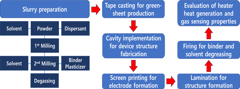
The manufacturing process of the sensor elements for the development of automotive nitrogen oxide (NOx) sensors is shown in Fig. 1.
2.1 Ceramic Raw Material Powder
In the tape-casting ceramic molding method, fine powdered ceramic raw materials with a particle diameter of 3 μm or less are used. When manufacturing ceramic sheets using the blade molding method, the composition of the raw material powder, particle size, and distribution of the particle size are significantly influenced by the ultimate sensor element; therefore, it is necessary to consider the characteristics of the starting material to manufacture sheets with excellent sinterability. In this experiment, commercially available YSZ powder (Inframat Advances Materials, LLC 99.95+% / Tosoh, 99.9+%) was used to prepare a green sheet for the solid electrolyte, a mixture of YSZ powder was used as the solid electrolyte, and cordierite (2Al2O3-2MgO-5SiO2) powder of less than 9 wt% was used to prepare a green sheet for the porous diffusion barrier.
2.2 Selection of Starting Organic Additives
To produce sheets by tape-casting ceramic powders, proper additives must be mixed in appropriate quantities. These additives, which are mainly organic, impart strength and plasticity to the ceramic sheet, ensure uniform dispersion of the ceramic powder in the solvent, and significantly affect the properties of the ceramic sheet during casting. Therefore, knowledge is acquired through repeated experiments. Although the selection of organic additives is an important experimental process, a broad selection criterion has not yet been established; hence, proper organic additives were selected through experiments for basic research.
2.3 Slurry Preparation and Tape Casting
Because the simultaneous addition of dispersants, plasticizers, and binders makes it difficult for organic matter to be competitively adsorbed onto the surface of the particles, thereby preventing complete dispersion, a homogeneous slurry was prepared by first mixing the solvent, dispersant, and YSZ powder with zirconia balls, followed by a second mixing with binders and plasticizers. In this experiment, MEK+Ethanol was used as a solvent, PEG was used as a dispersant and binder to maintain the strength of the sheet, and DBP was used as a plasticizer to loosen the bonds and impart plasticity to the sheet to prepare a slurry for tape casting. As the bubbles generated by the vapor pressure of air and solvent entering the slurry cause defects in the sheet, the slurry was subjected to a defoaming process by stirring at a constant speed under reduced pressure to remove the bubbles and excess solvent added for mixing, and to obtain a viscosity suitable for molding tape castings. The defoamed slurry was tape-cast and molded using a doctor blade. The tape carrier film was a polyethylene film with a thickness of 100 μm and a width of 170 mm, coated with SiO2 on the surface. The tape transport speed was 30 cm/min and blade height was 1.65 mm for the first and 1.15 mm for the second.
2.4 Processing of Green Sheet
The prepared green sheets were cut to fit the size of the sensor elements. In this experiment, the green sheet for the solid electrolyte was first cut to a size of 7 mm × 80 mm, and then the two cavity layers in the device were cut to the appropriate size. The cutting machine was an STC-10B (Hansung Systems, Inc.).
An experiment was conducted to print patterns, such as heaters, reference electrodes, and sensing electrodes, on a green sheet after cutting. The panel used for printing was divided into different materials to minimize the loss of paste during printing, as shown in Fig. 4. In addition, in the case of green sheets printed on both sides, drying was performed in an oven at 50°C for 10 min after printing on one side to prevent damage to the pattern.
After printing, lamination was performed to integrate the green sheets. Lamination was performed by varying pressure, temperature, and holding time based on the structural diagram of the manufactured sensor element. Depending on the condition of the green sheet, the temperature was 40–120°C, the pressure was 10–150 kgf/cm2, and the holding time was 1–60 min to ensure that the sensor element was not deformed.
The NOx sensor elements fabricated through lamination were subjected to heat treatment. The most important part of the heat treatment step is to degrease the amount of various organic solvents used during the green sheet manufacturing and establish conditions that can prevent cracking, bending, and warping of the device during heat treatment. For this purpose, the removal temperature of the organic solvent and shrinkage temperature of the green sheet were determined prior to heat treatment. In addition, the damage caused by the direct heat applied to the sample during heat treatment was prevented.
3. RESULTS AND DISCUSSIONS
3.1 Green Sheet of Ion Conducting Layer and Diffusion Barrier Layer
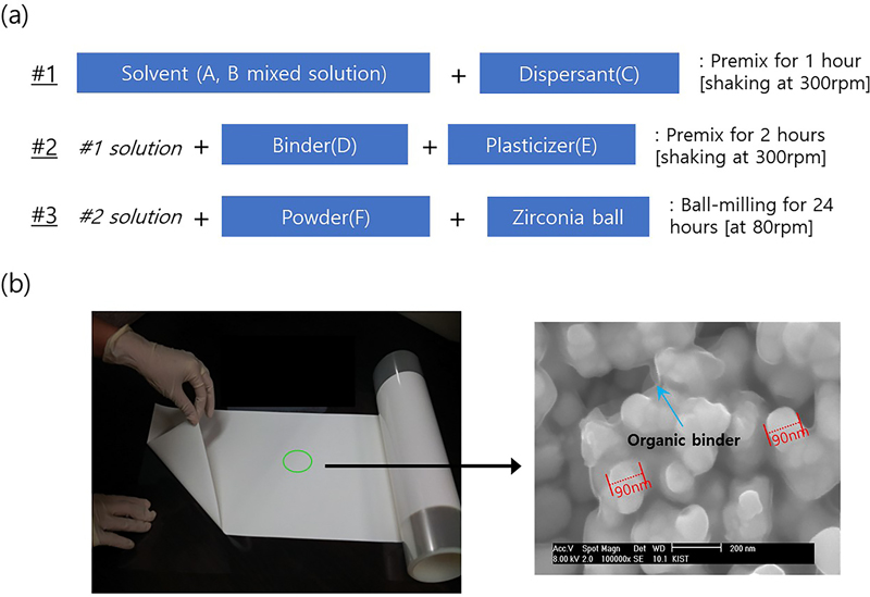
The two types of green sheets used in this study are solid electrolyte layer for ionic conduction and diffusion barrier layer. Because complete solubility could not be obtained when using a single solvent alone, good solubility results were obtained using mixed solvents. In addition, plasticizers were used appropriately to control viscosity and suppress adhesion to the film. The plasticizers contained in the green sheet decompose during heat treatment to prevent cracking of the green sheet owing to interaction with each other when it burned [14,15]. A 30 cm × 100 cm pilot green sheet without cracks was manufactured by adjusting the type and amount of the binder and organic solvent. Fig. 2 (a) shows the mixing sequence and proportions of the solvent, binder, dispersant, and plasticizer used to prepare the green sheet. Fig. 2 (b) shows a sample of the prepared green sheet and its structure obtained using SEM analysis.
3.2 Detector Electrode Manufacturing
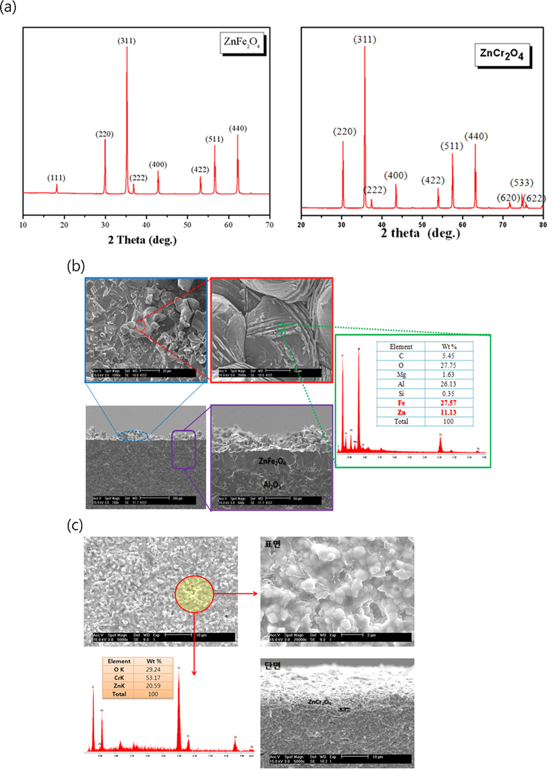
ZnFe2O4 and ZnCr2O4 were selected as sensing materials. Using ZnO (Aldrich Chemical Co, Ltd 99.9%), Fe2O3 (Aldrich Chemical Co. Ltd., 99.9%), and Cr2O3 (Aldrich Chemical Co. Ltd., 99.9%) as starting materials, Zn:Fe or Zn:Cr in a molar ratio of 1:2 was mixed using a wet ball mill for 24 h and then heat treated at 1600°C for 4 h to obtain synthesized ZnFe2O4 and ZnCr2O4. Fig. 3 (a) shows the XRD patterns of the synthesized ZnFe2O4 and ZnCr2O4 powders [16]. All synthesized powders exhibited single-phase spinel crystal structures.
The sensing electrode powders were mixed with the solvents and binders listed in Table 1, and prepared as a paste in a three-roll mill. The paste thus prepared was applied to alumina by screen printing method and dried at 50°C for 30 min [17,18]. The dried paste was heat treated at 1600°C to form a sensing electrode and analyzed by SEM and EDS to confirm its printability and composition (Figs. 3 (b) and 3 (c)).
3.3 NOx Sensor Structure Design and Fabrication
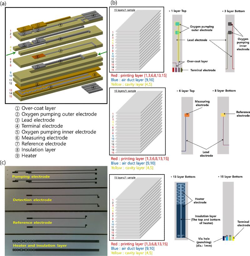
The NOx sensor device for automotive use was designed to improve the oxygen pumping efficiency and detection of NO and NO2 using a diffusion barrier layer, as shown in Fig. 4 (a) [19,20]. The designed NOx sensor is a next-generation NOx sensor with improved sensitivity achieved by controlling the oxidation-reduction rate of NO and NO2 on the oxide sensing electrode to improve the detection of NO and NO2 by improving the oxygen pumping efficiency and using a diffusion barrier layer, as shown in Fig. 4 (a) [21]. The nitrogen oxide sensor was designed using 15 green sheets. Each layer has a complex structure, as shown in Fig. 4 (b). The top surface of the first layer consists of an external oxygen-pumping electrode, a terminal electrode, and a lead electrode, which are protected by a porous protective layer and an insulating layer. An internal oxygen-pumping electrode and lead electrode were formed underneath the third layer, and the exhaust gas cavity was separated into two parts. The sixth and eighth layers formed the detection and reference electrodes, respectively, and the air duct was the bottom layer. In the third layer, a heater is formed between the insulating layers. The bottom of the fifth layer is composed of terminal electrodes, including heater terminals, which must be precisely controlled during mass production. In addition, to reduce the defect rate of the sensor element, the process was optimized to prevent adhesion between the paste and the green sheet, and short circuit of each pattern. When printing the heater pattern embedded in the sensor element, insulation layers of 15–30 μm thickness were formed above and below the heater to prevent the deterioration of the heater due to the applied voltage and to block the leakage current from the detection cell or pumping cell. In addition, an insulating layer and a porous protective layer were simultaneously formed to protect the electrode and lead electrode responsible for oxygen pumping outside the sensor, and the sensor element was manufactured to significantly improve the sensing characteristics (Fig. 4 (c)).
3.4 Analysis of the Structure and Composition of the Sensor Element After Heat Treatment
After the heat-treated NOx sensor specimens were cut using a cutting machine, the solid electrolytic zirconia sheet, internal and external pumped Pt electrodes, and external lead electrodes were analyzed using an electron microscope (Figs. 5 (a-c)), and the external morphology of the NOx sensor after firing was observed using an optical microscope (Fig. 5 (d)). The results showed that the interior of the green sheet had a fairly good filling of organic additives and ceramic powder, with few cracks and residual organic matter. This indicates that the selection of the organic additives according to the ceramic powder is appropriate, and that the conditions of the green sheet are satisfied in that it is possible to form an electrode of a certain thickness in the green sheet state and that no burn-out, bending, or cracking occurs during the manufacture of the sensor element. In addition, the reference, pumping, and detection electrodes showed little volatilization or diffusion of the electrode, even after heat treatment.
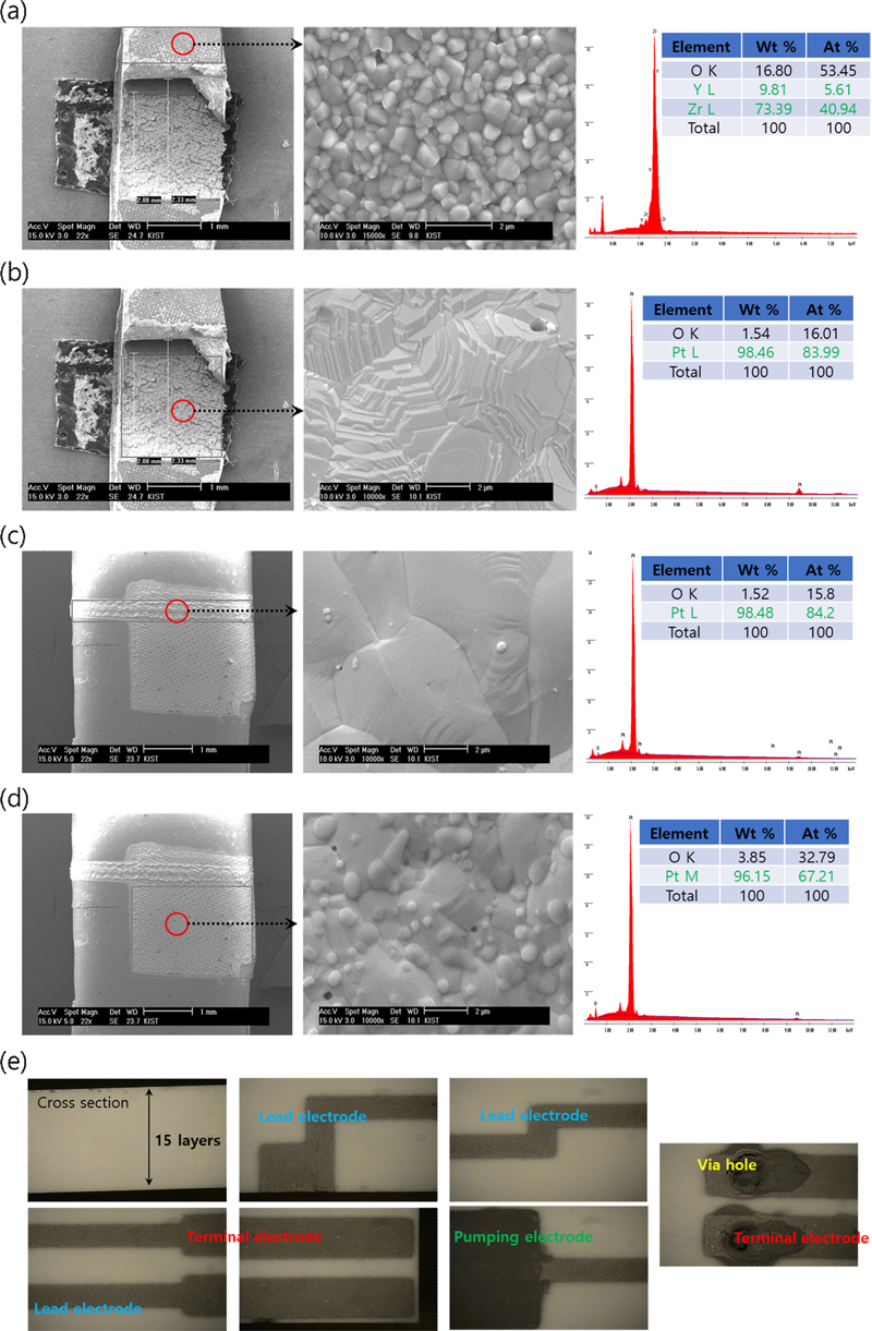
Microstructure and composition analysis images of (a) solid electrolytic zirconia sheet, (b) internally pumped Pt electrode, (c) externally pumped lead electrode, (d) externally pumped Pt electrode, and (e) optical microscopy image of the external shape of the sensor after firing
A test of the heater integrated into the nitrogen oxide sensor element was performed using an infrared thermal imaging camera. The temperature distribution of the entire sensor element and the temperature distribution of the heating area, where the oxygen-pumping, detection and reference electrodes were located, were investigated while maintaining 12 V. Fig. 6 (a) shows the infrared thermal imaging camera measurements, and Fig. 6 (b) shows the thermal test results of the fabricated nitrogen oxide sensor. Nitrogen oxide sensors directly measure the combustion gases in automotive exhaust, and hence, they should be able to operate at high temperatures of 700–800°C. As shown in Fig. 6 (b), the heater in the device is maintained at a temperature >800°C, which is sufficient for high temperature operation. Fig. 6 (c) shows the sensing signal as the NOx concentration changed under the conditions of 13–14% oxygen and 3% moisture. The results showed that a wide range of NOx concentrations can be detected and that the sensing signal changed stably with gas in/out. The time required for a sensor to detect a certain concentration of a test gas is called the response time; the faster the response time, the better the sensor. Figs. 6 (d-f) shows the response characteristics of the nitrogen oxide sensor at gas temperatures above 800°C as a function of time. The response time of the sensor obtained in this study was ON (at NOx 300 ppm): 2.29 s, ON (at NOx 1350–1500 ppm): 1.2 s, OFF (at NOx 0 ppm): 1.3 s, which is higher than that of the world's best sensor (NGK, 0.75 s); this is a very good result compared to the response time of most of the solid electrolyte sensors studied previously, which was more than 3 s.
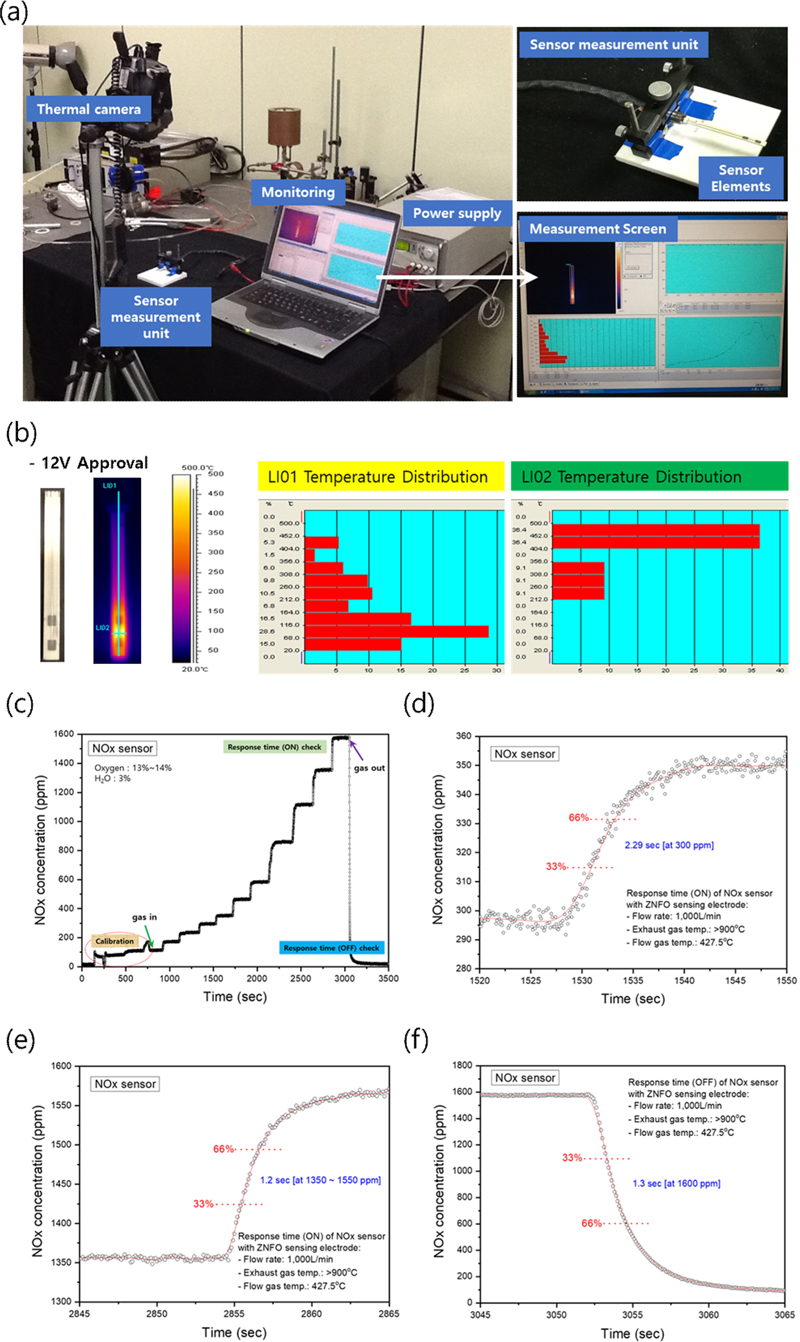
(a) Infrared thermal imaging camera measurement of sensor element, (b) heater heating test result of NOx sensor, (c) analysis of sensing signal according to NOx concentration change, (d) response characteristics of NOx sensor (ON, at NOx 300 ppm), (e) response characteristics of NOx sensor (ON, at NOx 1350–1500 ppm), and (f) response characteristics of NOx sensor (OFF, at NOx 0 ppm)
4. CONCLUSIONS
In this study, an automotive NOx sensor was developed by fabricating a solid electrolyte green sheet with ion conducting and diffusion barrier layers, which served as the foundation for producing the sensor component and assessing its high-temperature NO and NO2 sensing performance. The automotive NOx sensor structure was designed using a mixed-potential mechanism, which enables regulation of NO and NO2 redox reactions, while incorporating an internal heater, porous protective layers, and an insulation to prevent degradation and leakage current. The post-sintering analysis confirmed that electrode diffusion and cracking were effectively minimized, resulting in a uniform structure. Infrared thermography further verified that the heater maintained stable heat distribution at temperatures exceeding 800°C. In addition, NOx response characteristics were evaluated at gas temperatures above 800°C, and the sensor demonstrated a response time of 1.2–2.29 s, showing significant improvement in speed and stability compared to conventional solid electrolyte sensors. These results indicated that the developed NOx sensor could reliably detect NOx with high accuracy and speed under high-temperature conditions, indicating its practical applicability in automotive exhaust gas monitoring.
Acknowledgments
This research was supported by a grant of the Korea Evaluation Institute of Industrial Technology (KEIT) funded by the Korean government (MOTIE) (RS-2023-00257663), (RS-2023-00235283) and the Korea Institute of Industrial Technology (KITECH, Project no. UR240004).
REFERENCES
-
G. Coppola, V. Pugliese, and S. Chakraborty, “De-NOxSCR, catalysts and process designs in the automotive industry,” in Advanced technologies for solid, liquid, and gas waste treatment, Y.-C. Ho, W. J. Lau, S. Chakraborty, N. Rajamohan, and S. A. Arni, Eds. CRC Press, Boca Raton, 2023.
[https://doi.org/10.1201/9781003260738-14]

-
I. Nova and E. Tronconi, Urea-SCR technology for DeNOx after treatment of diesel exhausts, Part of the book series: Fundamental and applied catalysis (FACA), New York, Springer, NY, pp. 1-716, 2014.
[https://doi.org/10.1007/978-1-4899-8071-7]

-
S. C. Hill and L. Douglas Smoot, “Modeling of nitrogen oxides formation and destruction in combustion systems”, Prog. Energy Combust. Sci., Vol. 26, No. 4-6, pp. 417-458, 2000.
[https://doi.org/10.1016/S0360-1285(00)00011-3]

-
S. Madronich, M. Shao, S. R. Wilson, K. R. Solomon, J. D. Longstreth, and X. Y. Tang, “Changes in air quality and tropospheric composition due to depletion of stratospheric ozone and interactions with changing climate: implications for human and environmental health”, Photochem. Photobiol. Sci., Vol. 14, pp. 149-169, 2015.
[https://doi.org/10.1039/c4pp90037e]

-
I. S. Mudway and F. J. Kelly, “Ozone and the lung: a sensitive issue”, Mol. Aspects Med., Vol. 21, No. 1-2, pp. 1-48, 2000.
[https://doi.org/10.1016/S0098-2997(00)00003-0]

-
N. Hooftman, M. Messagie, J. V. Mierlo, and T. Coosemans, “A review of the european passenger car regulations – Real driving emissions vs local air quality”, Renewable Sustainable Energy Rev., Vol. 86, pp. 1-21, 2018.
[https://doi.org/10.1016/j.rser.2018.01.012]

-
Q. Li, W. Zeng, and Y. Li, “Metal oxide gas sensors for detecting NO2 in industrial exhaust gas: Recent developments”, Sens. Actuators B Chem., Vol. 359, p. 131579, 2022.
[https://doi.org/10.1016/j.snb.2022.131579]

-
P. K. Sekhar, Z. Moore, S. Aravamudhan, and A. Khosla, “A new low-temperature electrochemical hydrocarbon and NOx sensor”, Sensors, Vol. 17, p. 2759, 2017.
[https://doi.org/10.3390/s17122759]

-
M. C. Alvareza, S. F. Puertoa, P. Arroyo, C. M. Rodríguez, and E. P. Gil, “A portable, low-cost, smartphone assisted methodology for on-site measurement of NO2 levels in ambient air by selective chemical reactivity and digital image analysis”, Sens. Actuators B Chem., Vol. 338, p. 129867, 2021.
[https://doi.org/10.1016/j.snb.2021.129867]

-
O. L. Figueroa, C. Lee, S. A. Akbar, N. F. Szabo, J. A. Trimboli, P. K. Dutta, N. Sawaki, A. A. Soliman, and H. Verweij, “Temperature-controlled CO, CO2 and NOx sensing in a diesel engine exhaust stream”, Sens. Actuators B Chem., Vol. 107, No. 2, pp. 839-848, 2005.
[https://doi.org/10.1016/j.snb.2004.12.025]

-
J. Park, B. Y. Yoon, C. O. Park, W.-J. Lee, and C. B. Lee, “Sensing behavior and mechanism of mixed potential NOx sensors using NiO, NiO(+YSZ) and CuO oxide electrodes”, Sens. Actuators B Chem., Vol. 135, No. 2, pp. 516-523, 2009.
[https://doi.org/10.1016/j.snb.2008.10.006]

-
T. S. Kim, Y. B. Kim, K. S. Yoo, G. S. Sung, and H. J. Jung, “Sensing characteristics of dc reactive sputtered WO3 thin films as a NOx gas sensor”, Sens. Actuators B Chem., Vol. 62, No. 2, pp. 102-108, 2000.
[https://doi.org/10.1016/S0925-4005(99)00360-3]

-
M. Penza, C. Martucci, and G. Cassano, “NOx gas sensing characteristics of WO3 thin films activated by noble metals (Pd, Pt, Au) layers”, Sens. Actuators B Chem., Vol. 50, pp. 52-59, 1998.
[https://doi.org/10.1016/S0925-4005(98)00156-7]

-
Y.-J. Oh and C.-H. Lee, “Limit-current type zirconia oxygen sensor with porous diffusion layer”, J. Sens. Sci. Technol., Vol. 17, No. 5, pp. 329-337, 2008.
[https://doi.org/10.5369/JSST.2008.17.5.329]

-
T. Liu, X. Wang, L. Li, and J. Yu, “Review: Electrochemical NOx gas sensors based on stabilized zirconia”, J. Electrochem. Soc., Vol. 164, No. 13, pp. B610-B619, 2017.
[https://doi.org/10.1149/2.0501713jes]

-
S. Zhuiykov, T. Ono, N. Yamazoe, and N. Miura, “High-temperature NOx sensors using zirconia solid electrolyte and zinc-family oxide sensing electrode”, Solid State Ionics, Vol. 152-153, pp. 801-807, 2002.
[https://doi.org/10.1016/S0167-2738(02)00331-4]

-
R. Faddoul, N. R. Bruas, and A. Blayo, “Formulation and screen printing of water based conductive flake silver pastes onto green ceramic tapes for electronic applications”, Mater. Sci. Eng. B, Vol. 177, No. 13, pp. 1053-1066, 2012.
[https://doi.org/10.1016/j.mseb.2012.05.015]

-
M. V. Nikolic, Z. Z. Vasiljevic, M. D. Lukovic, V. P. Pavlovic, J. B. Krstic, J. Vujancevic, N. Tadic, B. Vlahovic, and V. B. Pavlovic, “Investigation of ZnFe2O4 spinel ferrite nanocrystalline screen-printed thick films for application in humidity sensing”, Int. J. Appl. Ceram. Technol., Vol. 16, No. 3, pp. 981-993, 2019.
[https://doi.org/10.1111/ijac.13190]

-
F. H. Garzon, R. Mukundan, and E. L. Brosha, “Solid-state mixed potential gas sensors: theory, experiments and challenges”, Solid State Ionics, Vol. 136-137, pp. 633-638, 2000.
[https://doi.org/10.1016/S0167-2738(00)00348-9]

-
T. Ritter, J. Zosel, and U. Guth, “Solid electrolyte gas sensors based on mixed potential principle: A review”, Sens. Actuators B Chem., Vol. 382, p. 133508, 2023.
[https://doi.org/10.1016/j.snb.2023.133508]

-
F. A. Ali, D. K. Mishra, R. Nayak, and B. Nanda, “Solid-state gas sensors: sensing mechanisms and materials”, Bull. Mater. Sci., Vol. 45, p. 15, 2022.
[https://doi.org/10.1007/s12034-021-02581-5]

