Magnetic and Crystallographic Properties of L10 FePt Thin Films in Contact with Ta and Pt Layers
This is an Open Access article distributed under the terms of the Creative Commons Attribution Non-Commercial License(https://creativecommons.org/licenses/by-nc/3.0/) which permits unrestricted non-commercial use, distribution, and reproduction in any medium, provided the original work is properly cited.
Abstract
The L10 FePt thin film is a magnetic material that is noteworthy for its application in the fabrication of ultra-high-density storage devices owing to its strong magnetic anisotropy and stable phase. Recently, it has been proposed that this alloy, which exhibits multilevel switching behavior, bulk spin current generation, and orbital current injection capabilities, could potentially serve as an ideal component in spin-orbit torque-driven devices. In this study, we examined the magnetic and crystallographic properties of FePt in contact with Ta and Pt layers, two conventionally used metals as spin-current sources. Our findings indicate that Ta forms a smooth interface but diminishes the perpendicular magnetic anisotropy of FePt, whereas Pt forms island-type growth that preserves this anisotropy. Moreover, we observed that the introduction of TaOx during FePt growth modified the surface and interface free energies, which was conducive to the formation of a flat Pt surface on FePt. This approach to controlling the free energy with oxides serves as a reference for growing spin-source materials and sets a precedent for future research on the development of spintronic devices based on novel material systems.
Keywords:
FePt, Ordered phase, Growth mechanism, Spin current source, Surface energy, Interface energy1. INTRODUCTION
Spin-orbit torque (SOT)-induced magnetization reversal has garnered significant attention owing to its numerous ideal characteristics, including fast switching, efficient power consumption, and high endurance [1-5]. Magnetic materials with high coercivity and strong perpendicular magnetic anisotropy (PMA) are particularly advantageous because they facilitate miniaturization and maintain a stable magnetization state with a 10-year retention [6-8]. L10 FePt is considered a particularly suitable material because of its high PMA (6.6 to 10 × 106 J/m3) [9-11]. This property originates from the strong coupling between the spin and orbital angular momenta, as well as the hybridization between Pt 5d orbitals and Fe 3d electrons. Pt, with its strong spin-orbit coupling, forms a spin-polarized electron structure under the influence of Fe, generating an orbital moment of approximately 0.1 μB. Consequently, the hybridization between Fe and Pt in FePt creates several unoccupied states in the minority band, leading to the formation of orbital moments along the fct[001] axis. Particularly, the proximity effect of Pt polarizes the spin, contributing to orbital moment formation, which explains the high PMA of approximately 106 J/m3 [12]. Recently, FePt-based spintronic devices have demonstrated SOT-switching behavior with various types of spin-current injections [13-15]. However, detailed studies on the microscopic structure and resultant magnetic properties of FePt in contact with spin current sources, such as Pt, Ta, and W, remain limited.
In this study, we present an analysis of the crystallinity and magnetic properties of FePt grown as spin-current generation layers on L10 FePt. Specifically, we examined and analyzed the growth mechanism of each material based on the surface energy of the MgO substrate, the volume energy of the L10 FePt layer, and interfacial energy differences. Additionally, we observed that the Pt layer exhibited island growth, whereas the addition of oxide to the FePt layer during growth significantly improved the surface roughness of the thin film.
2. EXPERIMENTAL
L10 FePt films with thicknesses ranging from 1 to 5 nm were epitaxially grown on MgO (001) single-crystal substrates using a direct-current (DC) magnetron sputtering system (AJA). The base and working pressure were maintained below 2 × 10⁻⁸ Torr and 3 × 10⁻³ Torr, and it was designed to accommodate up to 8 targets for deposition. The deposition rates of the targets were calibrated using X-ray reflection (XRR) measurements, which allowed control over the thin-film thickness by calculating the deposition time. A DC power supply was used for the metallic targets, whereas a radio-frequency (RF) power supply was used for the oxide targets to generate the plasma. The distance from the substrate to the target was approximately 13 cm, and the substrate was rotated during deposition to enhance film uniformity. The FePt alloy was deposited by co-sputtering Fe and Pt targets, and the confirmed nominal compositions of Fe and Pt in FePt were 51 and 49 atomic percent (at%), respectively. Before the deposition, the MgO substrate was immersed in butanone and sonicated for 15 min to remove any substances attached to the surface.
Subsequently, it was heat-treated at 650°C for 30 min inside the chamber to completely remove the moisture and impurities. The transport properties were measured using an electrical measurement system using a 2.7-T magnet with a sweeping out-of-plane external magnetic field (Hz) under a DC current of 1 mA. X-ray diffraction (XRD) spectrum analysis and high-angle annular darkfield scanning transmission electron microscopy (HAADFSTEM) were performed to confirm epitaxial growth. To analyze the microstructures of the films, HAADF-STEM specimens were prepared using a focused ion beam system (Helios NanoLab G3 UC (FEI)). HAADF-STEM images were captured using a Themis Z microscope (Thermo Fisher) at the Institute of Next-generation Semiconductor Convergence Technology, Daegu-Gyeongbuk Institute of Science and Technology (DGIST).
3. RESULTS AND DISCUSSIONS
3.1 Growth temperature and thickness dependence of magnetic property of the L10 FePt thin films
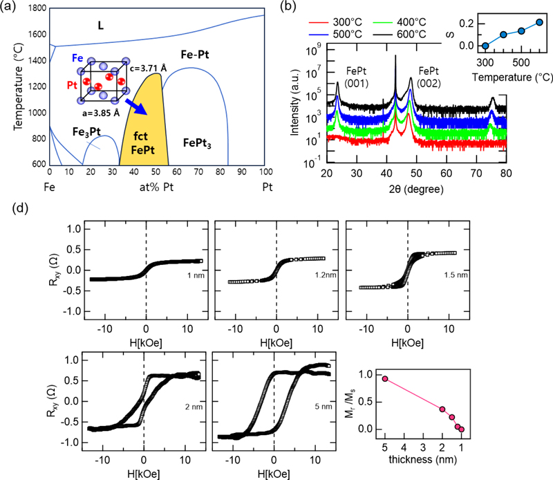
Fig. 1(a) presents the phase diagram of the FePt alloy [16]. FePt alloys can exist in three distinct phases depending on the Fe ratio and temperature: A1, L10, and L12. Fe3Pt and FePt3 compounds assume the L12 structure, FePt assumes the L10 structure as an ordered phase with a periodic arrangement, and the other FePt compounds exhibit a disordered A1 structure with random order. The L10 phase exhibited the highest PMA. As shown in the phase diagram, the L10 FePt phase is thermally stable below 1300°C but adopts the A1 structure below 400°C owing to kinetic constraints. This implies that a temperature above 600°C is required for the phase transformation from A1 to L10 through volume diffusion [17].

(a) Illustration of an equilibrium phase diagram of the Fe-Pt system. Schematic crystallographic structures of the ordered phase are shown in the corresponding phase equilibrium regions. (b) X-ray diffraction patterns of the FePt alloy prepared at 300°C, 400°C, 500°C, and 600°C. The inset shows the obtained S parameter as a function of temperature. (d) Thickness-dependent RAHE of FePt/MgO films and Mr/Ms values as a function of FePt thickness.
The Fe composition was first confirmed as it is crucial for the formation of the L10 FePt phase. Fig. 1(a) demonstrates that the Fe composition range favorable for the growth of the L10 FePt structure lies within 35–50%. We employed a co-sputtering method using an eight-target sputtering system, depositing Fe and Pt targets simultaneously. By fixing the Fe power and adjusting the Pt power, we controlled the alloy composition ratio, and to achieve the essential high temperature for L10-ordered FePt, a high temperature was applied during deposition. The Fe composition was confirmed using energy-dispersive X-ray spectroscopy analysis, while crystallinity was evaluated at temperatures ranging from 300°C to 800°C using XRD measurements. The XRD results in Fig. 1(b) indicate that the S parameter, calculated from the ratio of ordered to disordered phases, was highest at 600°C, indicating optimal crystallinity. The calculated S parameter was derived using the following formula:
| (1) |
After optimizing the experimental conditions for the ordered L10 phase, the magnetic properties of the samples were examined. For SOT switching experiments, which are essential for applications in magnetic devices, the switching current, a critical parameter for energy efficiency, is defined by the following equation [18]:
| (2) |
According to this equation, the switching current is inversely proportional to the thickness of the ferromagnet, emphasizing the importance of reducing the thickness of the ferromagnet to enhance switching efficiency. Therefore, we investigated the thickness dependence of FePt. Fig. 1(c) plots the anomalous Hall effect (AHE) measurements of FePt films with varying thickness (tFePt) from 1 to 5 nm. The AHE resistance (RAHE) is proportional to the mz component of magnetization with respect to the current, and RAHE without an applied magnetic field (Hex) is termed remanent magnetization (Mr), whereas saturation magnetization is termed MS with Hex strong enough to saturate the magnetization of FePt. The R-H loops indicate that the ratio of Mr/Ms approaches zero at 1.2 nm, indicating that the PMA of the film with tFePt below 1.2 nm significantly weakens. In other words, as tFePt decreases, mz gradually decreases, leaving only the in-plane magnetization for tFePt< 1 nm. For efficient SOT switching, minimizing the thickness of the ferromagnetic layer while retaining strong PMA for high thermal stability is critical. Thus, in this study, a junction structure of 5-nm-thick FePt with Pt and Ta spin current sources was realized, achieving Mr/Ms= 1.
3.2 Different growth modes between Pt and Ta on the L10 FePt layers
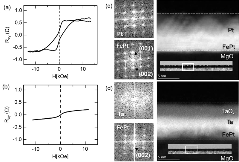
Figs. 2(a) and (b) depict the magnetic and crystalline characteristics of the samples grown with Pt and Ta, which serve as both the protective layer and the spin current source on the L10 FePt layer. Because RAHE is proportional to the mz of the magnetic film, it was expected that the magnetic characteristics would not differ significantly because of the dominant role of the ferromagnetic layer deposited identically in both samples. Contrary to this expectation, although the FePt layers were prepared in the same manner, the magnetic characteristics varied greatly depending on the spin source layers, as shown in Figs. 2 (a) and (b). In other words, PMA was observed in the Pt layer but disappeared in the Ta layer.

(a) RAHE-H curves of the Pt/FePt film and (b) RAHE-H curves of the Ta/FePt film. (c) FFT patterns and STEM-HAADF cross-sectional images of the FePt/Pt film. (d) FFT patterns and STEM-HAADF cross-sectional images of the FePt/Ta film.
To investigate the influence of the non-magnetic layer on magnetic properties, HAADF-STEM measurements were conducted as shown in Figs. 2(c) and (d). The results are clearly indicative of two outcomes: i) Pt islands epitaxially grown on the FePt; ii) amorphous-like Ta continuous layer on the FePt layer breaking the L10 FePt structure near the interface. Through a fast Fourier transformation (FFT) analysis of each layer, it was confirmed that the Pt-capped FePt film (FePt/Pt) exhibits a (001)-ordered pattern, while the Ta-capped film (FePt/Ta) demonstrates only a (002)-disordered pattern; these differences are attributed to the significant differences in their surface roughness and interface. In the former case, island growth led to noticeable surface unevenness, but the interface remained sharp. In the latter case, the Ta layer was grown amorphously on the FePt layer, resulting in an overall flat and continuous surface with severe intermixing at the interface. L10 FePt, with its high PMA and excellent thermal stability, has found wide use in devices as well as in high-density magnetic recording applications, such as hard disk drives and other data storage devices. For the SOT devices, both the strong PMA of FePt/Pt and the smooth surface quality of FePt/Ta are essential. These growth characteristics are a product of the balance between surface and interface energies. To control both energies, TaOx was added during the deposition of the FePt layer simultaneously.
3.3 Improved surface roughness of Pt with L10 FePt-TaOx thin film
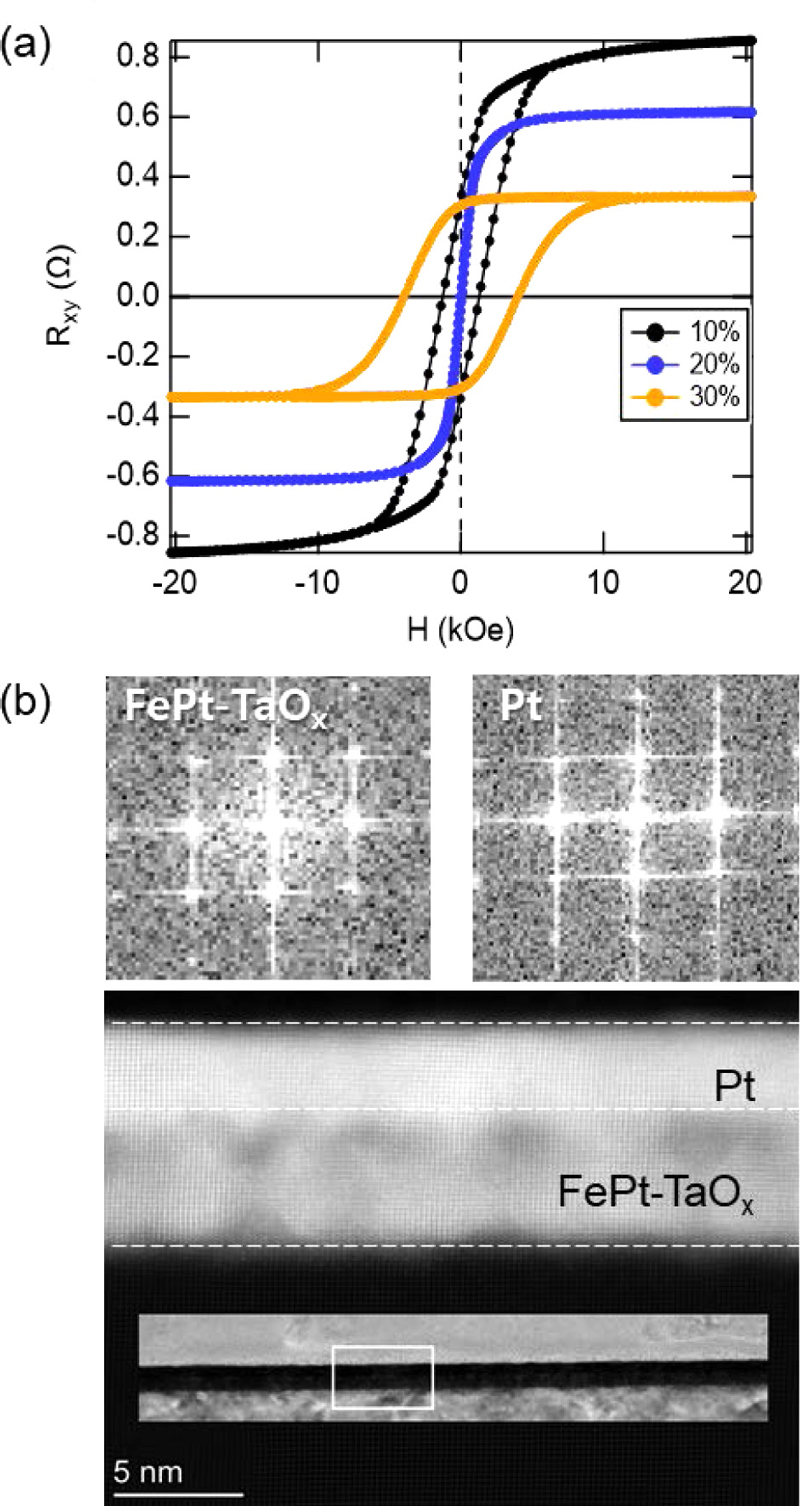
As illustrated in Fig. 3(a), the FePt-TaOx film exhibited a clear PMA with ~4 kOe coercivity and Mr/Ms of 1 with 30% TaOx. When the TaOx fraction was below 30%, the PMA weakened. This implies an optimal fraction of TaOx with a strong PMA. In contrast, the RAHE tended to decrease as the TaO fraction increased, indicating that TaOx was well mixed with the FePt phase, as expected. The HAADF-STEM image in Fig. 3(b) shows that Fe and Pt form the L10 FePt phase, growing in a grain shape with excellent crystallinity and an oxide-filling area, which leads to the continuous and epitaxial growth of Pt. The Pt surface was atomically flat. This observation suggests that, as intended, the addition of the oxide altered the surface energy between the materials, resulting in a completely different growth mechanism from that of the reference sample. Further analysis is discussed in the following paragraphs.
3.4 Free energy analysis to characterize the growth mode of Pt and Ta on L10 FePt films
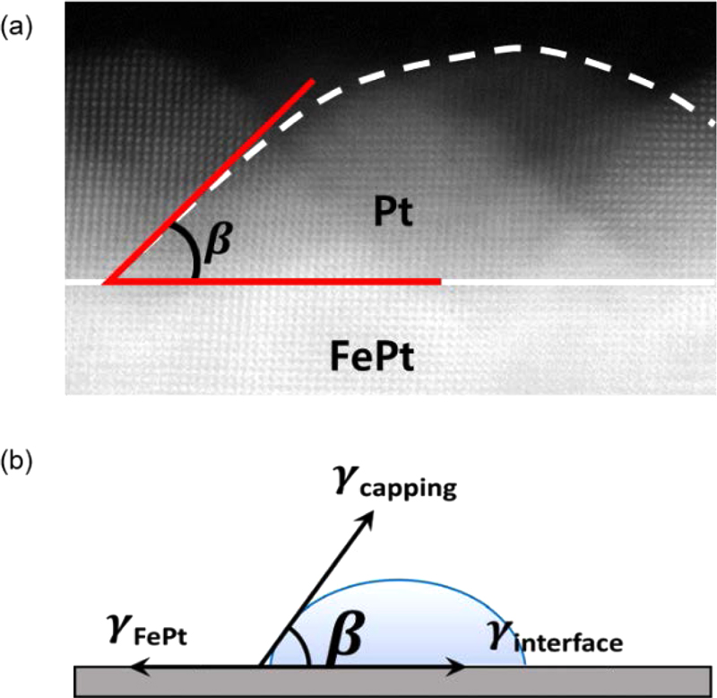
The growth mechanisms of each material were analyzed based on the free energy differences, considering the surface energy of the MgO substrate, the volume energy of the FePt layer, and the interfacial energy of each structure. As illustrated in Fig. 4(a), the relationship between the energies is:
| (3) |

(a) Island formation of Pt observed through HAADF-STEM imaging. (b) A schematic illustration depicting the orientation of the FePt surface, capping layer surface, and interface energies following the droplet formation on the FePt layer.
where γ is the free energy and β is the angle between the island surface and interface. Based on the HAADF-STEM image of FePt/Pt, a β value of 45° was directly determined. Thus, Eq. (3) translates to γFePt= γFePt/Pt+ γPt·cos45°. As γFePt ~2.90 J/m2 [19] and γPt ~2.45 J/m2 [20], γFePt/Pt= 1.22 J/m2. Those three surface energies compete with each other, resulting in the contact angle β of the droplet. This is the physical origin of island growth of the Pt layer on L10 FePt. In the case of the continuous film with β~0, cosβ = (γFePt−γFePt/Ta)/γTa ~1. Therefore, γFePt/Ta is negligible because γTa ~2.90 J/m2 [21]. Upon comparing two cases between Pt and Ta, we observed that γFePt/Pt >> γFePt/Ta. Ta atoms intermixed to reduce the interface energy, whereas Pt atoms did not diffuse into FePt. This observation explains the strong PMA exhibited by FePt/Pt maintaining the sharp interface and L10 structure.
In the case of the FePt-TaOx/Pt, a continuous film, γFePt-TaOx−γinter~γPt. Based on this relation, we conclude that the FePt-TaOx/Pt film satisfies the relation γFePt-TaOx−γFePt-TaOx/Pt ~2.3 J/m2. As γFePt−γFePt/Pt= 1.6 J/m2, the difference between the surface and interface energies increased after the addition of TaOx. This increase explains why the FePt–TaOx/Pt film achieves a flat surface.
4. CONCLUSIONS
This study investigated the growth of spin-source layers on a FePt layer, which is considered a highly promising magnetic material owing to its high PMA. Crystallographic analysis revealed that Pt formed an amorphous, continuous layer that disrupted PMA as a result of interfacial mixing near the interface. To address issues related to interfacial and surface roughness in these layers, TaOx was introduced during FePt growth. This addition altered the surface energies, yielding a smooth, epitaxial growth of the Pt protective layer on FePt without compromising the PMA. This approach to controlling free energy offers a pathway for growing spin-source materials, advancing the development of spintronic devices based on novel material systems.
Acknowledgments
This work was supported by the National Research Foundation of Korea (NRF), funded by the Korean government (MSIT) (No. RS-2024-00410027), the research program for future technologies by Hyundai Motor Group and Samsung Research Funding & Incubation Center of Samsung Electronics under Project Nos. SRFC-MA2401-02, and SRFC-MA2102-02.
REFERENCES
-
I. M. Miron, K. Garello, G. Gaudin, P.-J. Zermatten, M. V. Costache, S. Auffret, S. Bandiera, B. Rodmacq, A. Schuhl, and P. Gambardella, “Perpendicular switching of a single ferromagnetic layer induced by in-plane current injection”, Nature, Vol. 476, pp. 189-193, 2011.
[https://doi.org/10.1038/nature10309]

-
L. Liu, C.-F. Pai, Y. Li, H. W. Tseng, D. C. Ralph, and R. A. Buhrman, “Spin-Torque Switching with the Giant Spin Hall Effect of Tantalum”, Science, Vol. 336, No. 6081, pp. 555-558, 2012.
[https://doi.org/10.1126/science.1218197]

-
W. S. Ham, T. H. Ho, Y. Shiota, T. Iino, F. Ando, T. Ikebuchi, Y. Kotani, T. Nakamura, D. Kan, Y. Shimakawa, T. Moriyma, E. Im, N. Lee, K. Kim, S. C. Hong, S. H. Rhim, T. Ono, and S. Kim, “Bulk Rashba-Type Spin Splitting in Non-Centrosymmetric Artificial Superlattices”, Adv. Sci., Vol. 10, p. 2206800, 2023.
[https://doi.org/10.1002/advs.202206800]

-
J. Ryu, S. Lee, K. J. Lee, and B. G. Park, “Current-Induced Spin-Orbit Torques for Spintronic Applications”, Adv. Mater., Vol. 32, No. 35, p. 1907148, 2020.
[https://doi.org/10.1002/adma.201907148]

-
Q. A. T. Nguyen and S. H. Rhim, “Spin Hall Conductivity of W100-xSix Alloys in A15 Structure: A Comprehensive Study”, J. Mag., Vol. 29, No. 2, pp. 155-159, 2024.
[https://doi.org/10.4283/JMAG.2024.29.2.155]

-
H. Meng and J.-P. Wang, “Spin transfer in nanomagnetic devices with perpendicular anisotropy”, Appl. Phys. Lett., Vol. 88, No. 17, p. 172506, 2006.
[https://doi.org/10.1063/1.2198797]

-
S. Ikeda, K. Miura, H. Yamamoto, K. Mizunuma, H. D. Gan, M. Endo, S. Kanai, J. Hayakawa, F. Matsukura, and H. Ohno, “A perpendicular-anisotropy CoFeB-MgO magnetic tunnel junction”, Nat. Mater., Vol. 9, pp. 721-724, 2010.
[https://doi.org/10.1038/nmat2804]

-
H. Sato, M. Yamanouchi, K. Miura, S. Ikeda, H. D. Gan, K. Mizunuma, R. Koizumi, F. Matsukura, and H. Ohno, “Junction size effect on switching current and thermal stability in CoFeB/MgO perpendicular magnetic tunnel junctions”, Appl. Phys. Lett., Vol. 99, p. 042501, 2011.
[https://doi.org/10.1063/1.3617429]

-
T. J. Klemmer, N. Shukla, C. Liu, X. W. Wu, E. B. Svedberg, O. Mryasov, R. W. Chantrell, D. Weller, M. Tanase, and D. E. Laughlin, “Structural studies of L10 FePt nanoparticles”, Appl. Phys. Lett., Vol. 81, No. 12, pp. 2220-2222, 2002.
[https://doi.org/10.1063/1.1507837]

-
S. H. Whang, Q. Feng, and Y. Q. Gao, “Ordering, deformation and microstructure in L10 type FePt”, Acta Mater., Vol. 46, No. 18, pp. 6485-6495, 1998.
[https://doi.org/10.1016/S1359-6454(98)00311-5]

-
G. Varvaro, S. Laureti, and D. Fiorani, “L10 FePt-based thin films for future perpendicular magnetic recording media”, J. Magn. Magn. Mater., Vol. 368, pp. 415-420 2014.
[https://doi.org/10.1016/j.jmmm.2014.04.058]

-
A. Kabir, J. Hu, V. Turkowski, R. Wu, R. Camley, and T. S. Rahman, “Effect of structure on the magnetic anisotropy of L10 FePt nanoparticles”, Phys. Rev. B, Vol. 92, No. 5, p. 054424, 2015.
[https://doi.org/10.1103/PhysRevB.92.054424]

-
M. Tang, K. Shen, S. Xu, H. Yang, S. Hu, W. Lü, C. Li, M. Li, Z. Yuan, S. J. Pennycook, K. Xia, A. Manchon, S. Zhou, and X. Qiu, “Bulk Spin Torque-Driven Perpendicular Magnetization Switching in L10 FePt Single Layer”, Adv. Mater., Vol. 32, No. 31, p. 2002607, 2020.
[https://doi.org/10.1002/adma.202002607]

-
Y. Tao, C. Sun, W. Li, C. Wang, F. Jin, Y. Zhang, Z. Guo, Y. Zheng, X. Wang, and K. Dong, “Spin-Orbit Torque-Driven Memristor in L10 FePt Systems with Nanoscale-Thick Layers for Neuromorphic Computing”, ACS Appl. Nano Mater., Vol. 6, No. 2, pp. 875-884, 2023.
[https://doi.org/10.1021/acsanm.2c04094]

-
H. Lyu, Y. Zhao, J. Qi, H. Huang, J. Zhang, G. Yang, Y. Guo, S. Shen, W. Qin, Y. Sun, and J. Shen, “Field-Free Magnetization Switching Driven by Spin-Orbit Torque in L10-FeCrPt Single Layer”, Adv. Funct. Mater., Vol. 32, No. 30, p. 2200660, 2022.
[https://doi.org/10.1002/adfm.202200660]

-
Y. Q. Gao, Z. M. Wang, and S. H. Whang, “Deformation behavior in L10-type FePt compound”, Mater. Sci. Eng., Vol. A192-193, pp. 53-58, 1995.
[https://doi.org/10.1016/0921-5093(94)03203-3]

-
I. Zafiropoulou, V. Tzitzios, N. Boukos, and D. Niarchos, “Ordering kinetics of chemically synthesized FePt nanoparticles”, J. Magn. Magn. Mater., Vo. 316, No. 2, pp. e169-e172, 2007.
[https://doi.org/10.1016/j.jmmm.2007.02.072]

-
K. S. Lee, S. W. Lee, B. C. Min, and K. J. Lee, “Threshold current for switching of a perpendicular magnetic layer induced by spin Hall effect”, Appl. Phys. Lett., Vol. 102, No. 11, p. 112410, 2013.
[https://doi.org/10.1063/1.4798288]

-
I. Suzuki, S. Kubo, H. Sepehri-Amin, and Y. K. Takahashi, “Dependence of the Growth Mode in Epitaxial FePt Films on Surface Free Energy”, ACS Appl. Mater. Interfaces, Vol. 13, No. 14, pp. 16620-16627, 2021.
[https://doi.org/10.1021/acsami.0c22510]

-
H. Seo, A. B. Posadas, and A. A. Demkov, “First-principles study of the growth thermodynamics of Pt on SrTiO3 (001)”, J. Vac. Sci. Technol. B, Vol. 30, No. 4, p. 04E108, 2012.
[https://doi.org/10.1116/1.4732461]

-
A. Kiejna, “Surface atomic structure and energetics of tantalum”, Surf. Sci., Vol. 598, No. 1-3, pp. 276-284, 2005.
[https://doi.org/10.1016/j.susc.2005.09.029]

